Apparatus and method for implantation of surgical devices

a surgical device and apparatus technology, applied in the field of apparatus and methods for implanting surgical devices, can solve the problems of increasing the size or width of the coupling element, and causing damage to surrounding tissues, so as to avoid threaded connections, increase the effect of surgical devices, and increase the size of surgical devices

Inactive Publication Date: 2013-01-01
PIONEER SURGICAL TECH INC
View PDF16 Cites 42 Cited by
  • Summary
  • Abstract
  • Description
  • Claims
  • Application Information

AI Technical Summary

Benefits of technology

[0011]In accordance with one aspect, an apparatus is disclosed for securing with and generally immobilizing in a pre-determined relative orientation an anchor or screw and a pivotable coupling member of a surgical device such as a spinal rod fixation device. In this manner, the coupling device and fixation device can be secured joined or driven into a bone such as a vertebrae without the coupling device and fixation device pivoting relative to each other. By restricting or eliminating the pivoting of the components of the surgical device, the size of the incision into the anatomy and through the surrounding tissues can be minimized, and damage to surrounding tissues as a result of rotating the surgical device is minimized.
[0012]Each of the coupling device and fixation device has a central longitudinal axis. When secured with the implantation device, the respective longitudinal axes are aligned with each other. The implantation device is received within the coupling device and fixation device so that it does not substantially exceed the profile and size of the surgical device itself. Thus, the surgical device has a single longitudinal axis, and the radial extent of the surgical device is generally that of the components of the surgical device and, typically, the radial extent of the coupling device. Again, securing the components of the surgical device with the implantation device in such a manner minimizes the size of the incision and resection of surrounding tissues.
[0014]With a typical screw and screwdriver cooperation, it is also commonly necessary for a surgeon's hand to position the screw tip at a desired implantation point or region, and to maintain the screw in proper alignment during at least an initial driving of the screw into a bone. The implantation device with the surgical device secured thereto allows a surgeon to use a second, guiding hand if desired by grasping an elongated body of the implantation device. Furthermore, the surgical device being secured is held in general alignment with the implantation device so that the proper alignment for screw itself is maintained. This allows the surgeon to operate without resecting tissues to an extent to permit a hand to be close to the implantation site for holding the screw or maintaining the screw in desired and proper alignment.
[0017]The present implantation device, accordingly, further permits the avoidance of threaded connections between closure members and coupling devices. It is presently believed that a threaded connection requires a greater axial length for the coupling device to be properly and securely joined with the closure member. The use of threads by the prior art system therefore requires a greater axial length then other connection designs, and this greater axial length increases the size of the surgical device and increases the effects of the surgical device when implanted in a body with surrounding tissues and with bio-mechanical motion.

Problems solved by technology

During installation, this polyaxial feature presents a number of issues.
This can be problematic as the coupling member may interfere with the rotational driving action, such as by binding with the driver and screw anchor, and this interference may inadvertently alter the position and orientation in which the shank is driven.
As the screw member turns with the coupling member tilted to one side, the coupling member may sweep around the implantation site potentially causing damage to surrounding tissues.
As is apparent, the polyaxial movement provided between the screw anchor and yoke coupling member can make the driving operation for implanting the screw into the vertebral bone more difficult than is desired.
Internally threading these walls necessitates that the walls be of sufficient thickness for forming threads therein, undesirably increasing the size or width of the coupling element, as well as the height of these walls along which the threads are formed.
Seating of the drive prongs in the corresponding recesses of the screw head is difficult due to the need to positively thread the driver into the coupling element.
Further, after the screw has been fully implanted in the pedicle of the vertebra, releasing the driver requires it be turned to back the shaft threads out from the coupling element threads, potentially loosening the implanted screw.

Method used


Image

  • Apparatus and method for implantation of surgical devices
  • Apparatus and method for implantation of surgical devices
  • Apparatus and method for implantation of surgical devices

Examples


Embodiment Construction

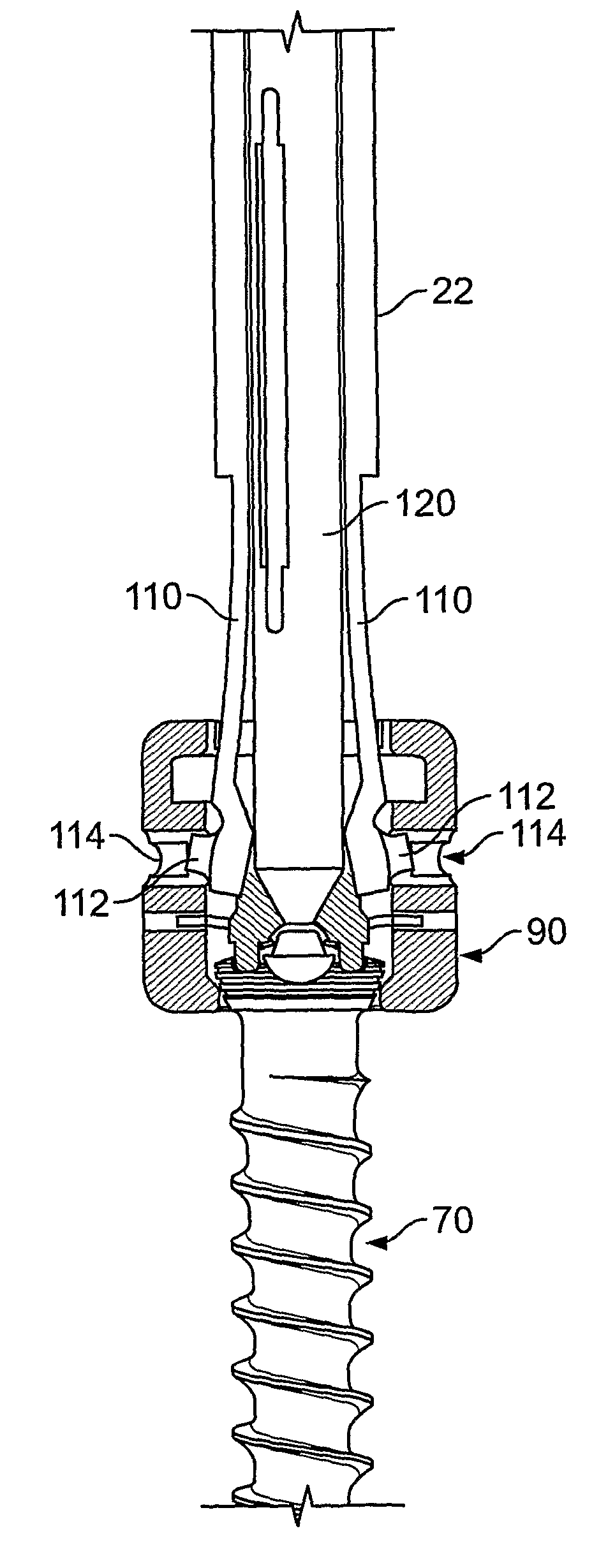
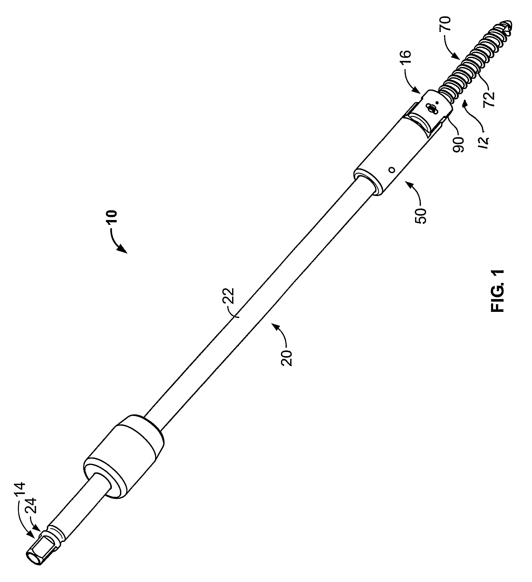
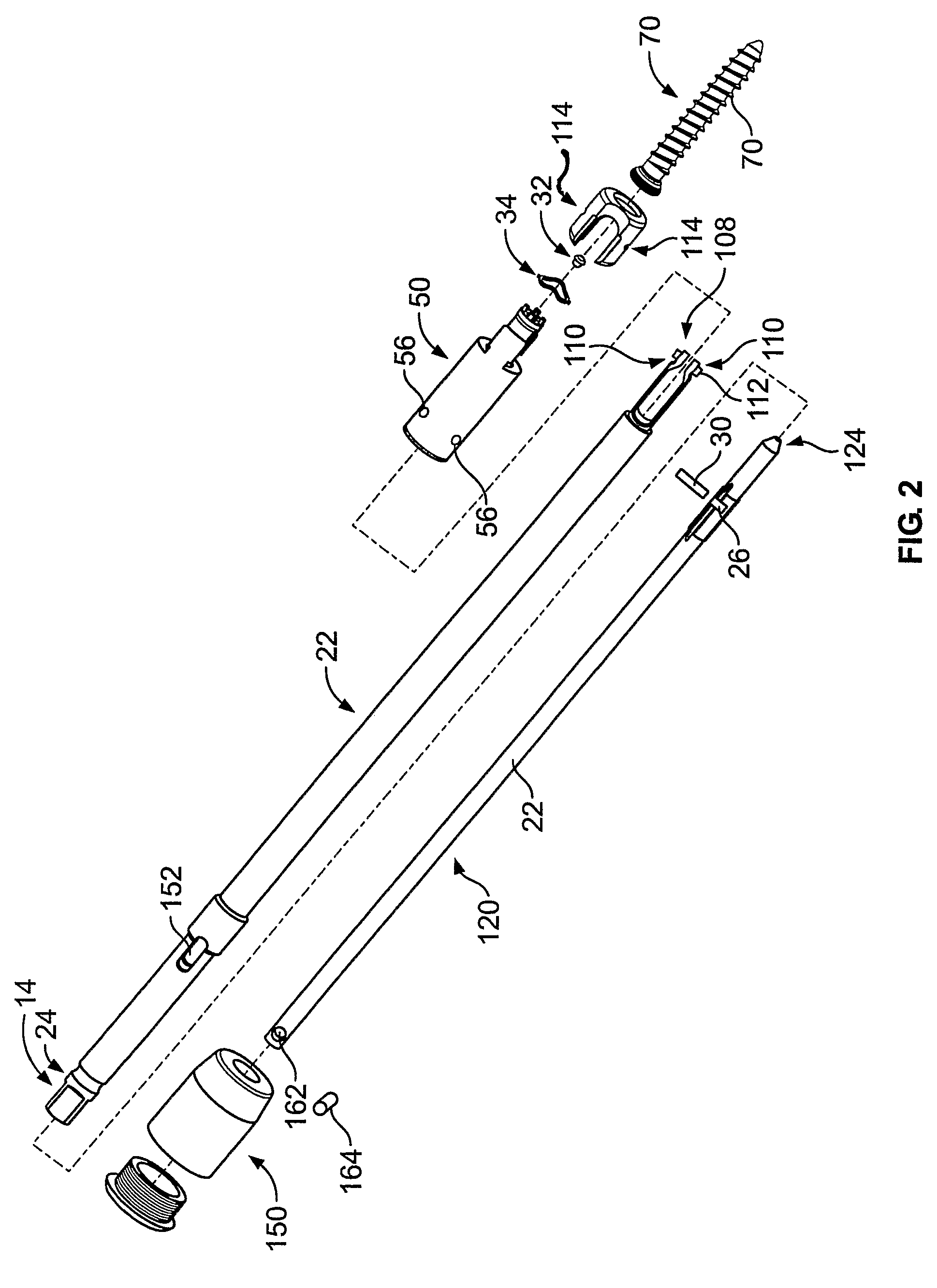
[0036]Referring initially to FIG. 1, a driving apparatus 10 is depicted for securing a fixation device 12 to a bone such as a vertebra. The implantation device 10 includes a proximal end portion 14 coupled with an operator handle (not shown) and a distal drive end portion 16 for being coupled with the fixation device 12.

[0037]The driving apparatus 10 includes a locking member 20 having a body 22 extending between the proximal end 14 and the distal end 16. The locking member 20 adjacent the proximal end 14 includes a non-circular end portion 24 for joining with the operator handle. For instance, the operator handle may include a socket (not shown) for receiving the end portion 24 so that rotation of the operator handle effects rotation of the locking member 20 and the implantation device 10.

[0038]The locking member body 22 is generally fixed with the drive end portion 16 of the apparatus 10 so that they are fixed for rotating together so that turning of the locking member 20 causes t...


PUM


Abstract

A driver apparatus for implanting spinal rod fixation devices including an anchor member and a coupling member pivotable relative to the anchor member is disclosed. The driver apparatus generally immobilizes the anchor member and coupling member relative to each other and to the driver apparatus during insertion to minimize interference between the coupling member and tissues surrounding the implantation site, as well as to minimize the clearance required for implantation. The driver apparatus includes a driver portion engageable with the anchor member for effecting seating of the anchor member, such as by threadably driving the anchor member in the bone. The driver portion is closely fit between portions such as upstanding walls of the coupling member to prevent relative rotation therebetween. The driver apparatus further includes locking portions shiftable to secure the coupling member with the driver apparatus when the driver is engaged with the anchor member.

Description

CROSS-REFERENCE TO RELATED APPLICATIONS[0001]This application is a U.S. national phase application filed under 35 U.S.C. § 371 of International Application PCT / US2006 / 037789, filed on Sep. 26, 2006, which claims priority from U.S. Provisional Application No. 60 / 720,955, filed on Sep. 26, 2005, which are hereby incorporated herein by reference in their entirety.FIELD OF THE INVENTION[0002]The invention relates to An apparatus and method for implanting surgical devices, in particular, for implanting and securing a fixation device to a bone, and, more particularly, to a driving apparatus and method for implanting an anchor of a spinal rod fixation device in a bone.BACKGROUND OF THE INVENTION[0003]There are currently a wide array of surgical devices for spinal surgery. One group of these devices includes a fixation device including a screw or hook anchor for securing the device to a vertebrae, such as the pedicle portion of the vertebra. Many of these surgical devices are spinal rod fix...

Claims


Application Information

Patent Timeline
Patent Type & Authority Patents(United States)
IPC IPC(8): A61B17/58
CPCA61B17/8875A61B17/7082A61B17/7037
Inventor BERREVOETS, GREGORY
Owner PIONEER SURGICAL TECH INC
Why Eureka
Try Eureka