Surge suppression circuit for a load control device

a technology of surge suppression and load control device, which is applied in the direction of overvoltage protection resistors, emergency protective arrangements for limiting excess voltage/current, and arrangements responsive to excess voltage, etc., can solve the problem of reducing affecting the ability of the surge suppression system to limit the magnitude of the surge voltage applied, and resonant ringing. problem, to achieve the effect of preventing noise generation and improving the protection of the load control devi

Active Publication Date: 2013-01-01
LUTRON TECH CO LLC
View PDF16 Cites 20 Cited by
  • Summary
  • Abstract
  • Description
  • Claims
  • Application Information

AI Technical Summary

Benefits of technology

[0008]According to an embodiment of the present invention, a surge suppression circuit for a load control device allows the load control device to pass hipot testing, while providing improved protection of the load control device during surge events. The load control device comprises a load control circuit and a filter circuit that has first and second connections adapted to receive an AC mains line voltage from an AC power source, and third and fourth connections adapted to be coupled to the load control circuit. The filter circuit has one or more inductive components, and is operable to prevent noise generated by the load control circuit from being provided to the AC power source. The surge suppression circuit comprises a clamping device electrically coupled between the first and second connections of the filter circuit, a first spark gap coupled between the first and third connections of the filter circuit for limiting the magnitude of the voltage generated between the first and third connections by the inductive components of the filter circuit, and a second spark gap coupled between the second and fourth connections of the filter circuit for limiting the magnitude of the voltage generated between the second and fourth connections by the inductive components of the filter circuit.
[0009]In addition, a load control system for controlling the power delivered from an AC power source to an electrical load is also described herein. The load control system comprises a load control circuit adapted to be coupled in series electrical connection between the AC power source and the electrical load for controlling the power delivered to the electrical load, and a filter circuit having first and second connections adapted to receive an AC mains line voltage from an AC power source, and third and fourth connections adapted to be coupled to the load control circuit. The filter circuit is operable to prevent noise generated by the load control circuit from being provided to the AC power source. The load control system further comprises a clamping device electrically coupled between the first and second connections of the filter circuit, a first spark gap coupled between the first and third connections of the filter circuit for limiting the magnitude of the voltage generated between the first and third connections, and a second spark gap coupled between the second and fourth connections of the filter circuit for limiting the magnitude of the voltage generated between the second and fourth connections.

Problems solved by technology

In addition, typical load control devices are also designed such that the electrical insulation between the electrical circuitry and the outer enclosure (which is typically connected to earth ground) is appropriate, such that the load control devices do not provide unsafe conditions for a user.
However, surge events can cause resonant ringing in the components of the RFI filter, which may greatly amplify the magnitude of the voltages applied to the electronic components 22.
Thus, the spark gap 26 negatively impacts the ability of the surge suppression system to limit the magnitude of the surge voltages applied to the electronic components 22.

Method used


Image

  • Surge suppression circuit for a load control device
  • Surge suppression circuit for a load control device
  • Surge suppression circuit for a load control device

Examples


Embodiment Construction

[0019]The foregoing summary, as well as the following detailed description of the preferred embodiments, is better understood when read in conjunction with the appended drawings. For the purposes of illustrating the invention, there is shown in the drawings an embodiment that is presently preferred, in which like numerals represent similar parts throughout the several views of the drawings, it being understood, however, that the invention is not limited to the specific methods and instrumentalities disclosed.

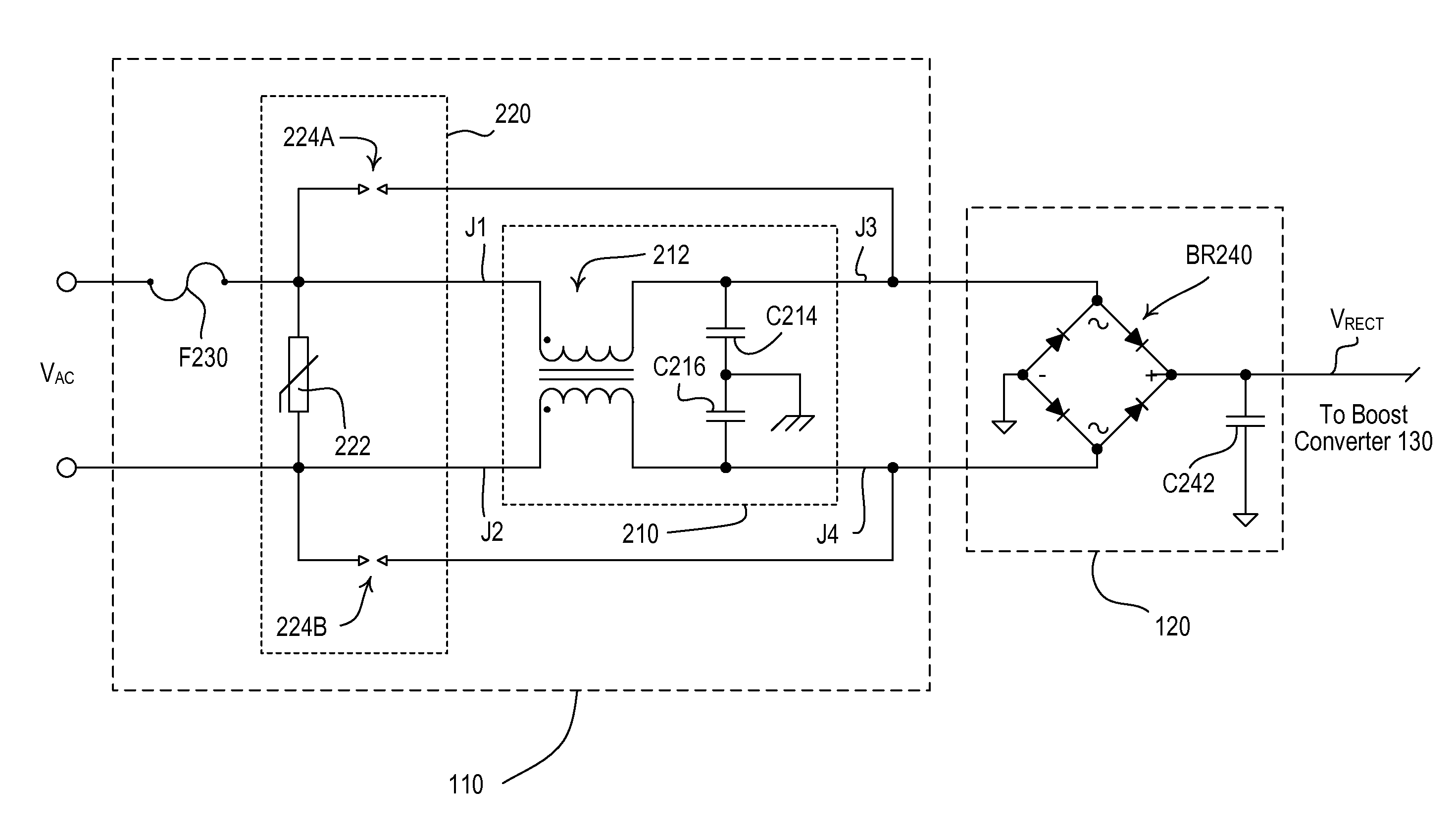
[0020]FIG. 2 is a simplified block diagram of an electronic dimming ballast 100 according to a first embodiment of the present invention. The ballast 100 comprises a hot terminal H and a neutral terminal N that are adapted to be coupled to an alternating-current (AC) power source (not shown) for receiving an AC mains line voltage VAC. The ballast 100 is adapted to be coupled between the AC power source and a gas discharge lamp (e.g., a fluorescent lamp 105), such that the ballas...


PUM


Abstract

A surge suppression circuit for a load control device allows the load control device to pass hipot testing, while providing improved protection of the load control device during surge events. The load control device comprises a load control circuit and a filter circuit for preventing noise generated by the load control circuit from being provided to an AC power source. The surge suppression circuit comprises a clamping device adapted to be electrically coupled across the AC power source, and first and second spark gaps coupled across the filter circuit for limiting the magnitude of the voltage generated by inductive components of the filter circuit. The filter circuit may comprise a common-mode choke, and two series-connected capacitor having their junction connected to earth ground. Alternatively, the filter circuit may additionally comprise a differential-mode choke.

Description

BACKGROUND OF THE INVENTION[0001]1. Field of the Invention[0002]The present invention relates to a surge suppression circuit for protecting an electrical load during surge events.[0003]2. Description of the Related Art[0004]A load control device is operable to control the amount of power delivered from an alternating-current (AC) power source to an electrical load, such as a lighting load or a motor load. Typical load control devices include, for example, dimmer switches for lighting loads, electronic ballasts for gas discharge lamps, light-emitting diodes (LED) drivers for LED light sources, and motor control devices for motor loads. Typical load control devices are designed to withstand surge events (i.e., transient spikes in voltage) that can occur on a power line as a result of inductive load switching, lightning strikes, and other transient events on the power line. Prior art load control devices have included voltage surge and voltage transient suppressors between the AC power...

Claims


Application Information

Patent Timeline
Patent Type & Authority Patents(United States)
IPC IPC(8): H02H1/04
CPCH02H9/005H02M1/12H02H9/06H02H7/008
Inventor VESKOVIC, DRAGAN
Owner LUTRON TECH CO LLC
Why Eureka
Try Eureka