Cooperative spatial multiplexing

a spatial multiplexing and co-operative technology, applied in the field of cooperative communications, can solve the problems of high resource consumption, limited and tightly regulated spectrum, and limited energy supply of wireless terminals, and achieve the effect of limited spectrum, energy and spa

Inactive Publication Date: 2013-01-01
IOWA STATE UNIV RES FOUND
View PDF16 Cites 55 Cited by
  • Summary
  • Abstract
  • Description
  • Claims
  • Application Information

AI Technical Summary

Benefits of technology

[0008]It is a further object, feature, or advantage of the present invention to provide for cooperative communications in a manner appropriate for high-rate data.
[0009]It is a further object, feature, or advantage of the present invention to provide for cooperative spatial multiplexing which only requires a source to have a single antenna.
[0010]Another object, feature, or advantage of the present invention is to provide for cooperative spatial multiplexing using a plurality of relay nodes, each requiring only a single antenna.
[0011]A still further object, fe...

Problems solved by technology

Future wireless communication environments are highly resource-constrained, offering a limited and tightly regulated spectrum.
The energy supply on wireless terminals is usually limited, and, in many scenarios they must operate for many years without battery replacement.
In many practical scenarios, space limitations at the terminal site make antenna spacing critical, a physical constraint that significantly limits the applicability of antenna arrays.
Despite the advantage of ...

Method used


Image

  • Cooperative spatial multiplexing
  • Cooperative spatial multiplexing
  • Cooperative spatial multiplexing

Examples


Embodiment Construction

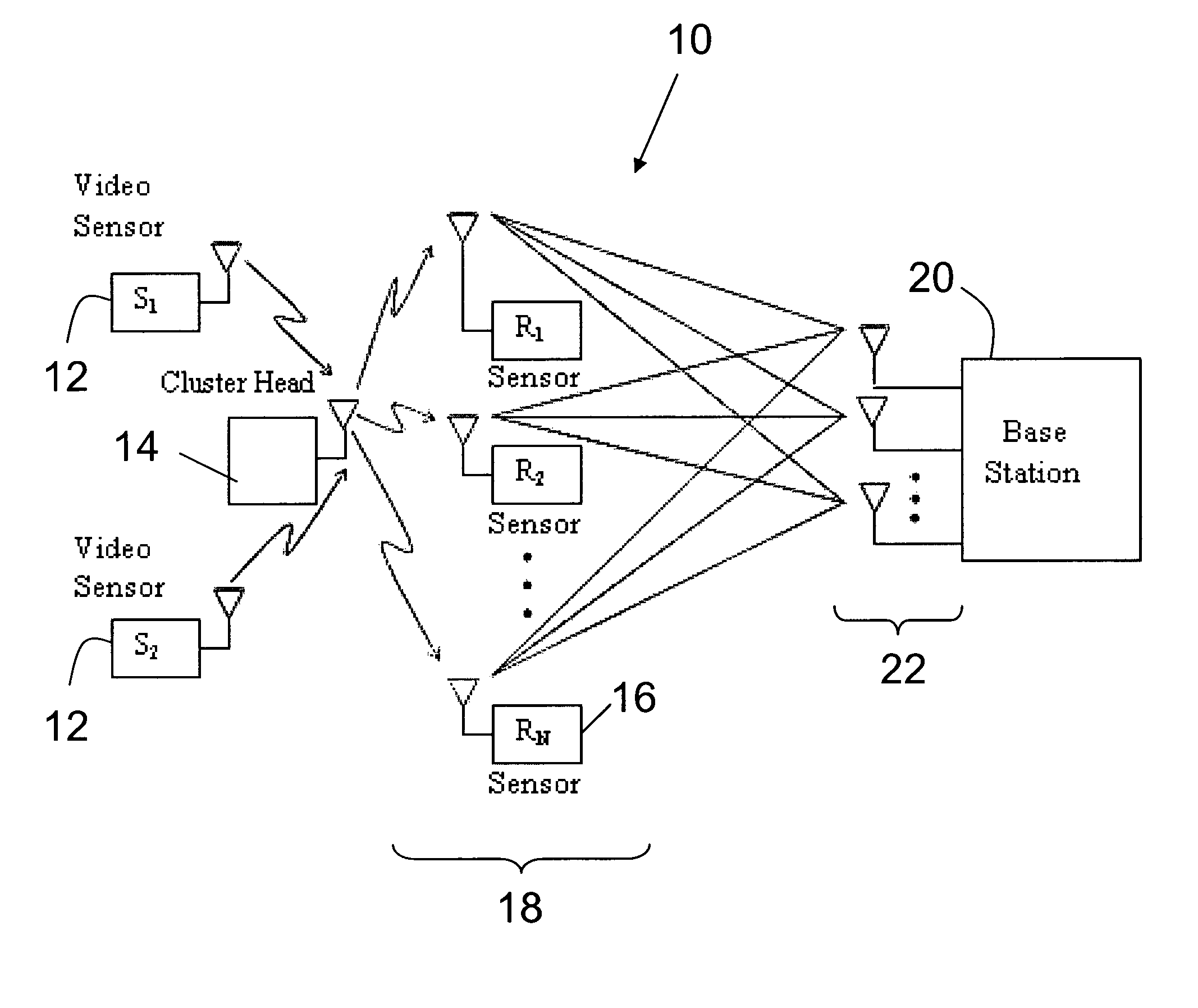
[0046]The present invention is now described with respect to exemplary embodiments. The present invention is not to be limited to the specific disclosure provided herein as the present invention contemplates numerous variations as may be appropriate in particular environments or contexts. A first embodiment is discussed with respect to a generalized communications network using cooperative spatial multiplexing. A second embodiment is discussed with respect to a cooperative relaying architecture for wireless video sensor networks.

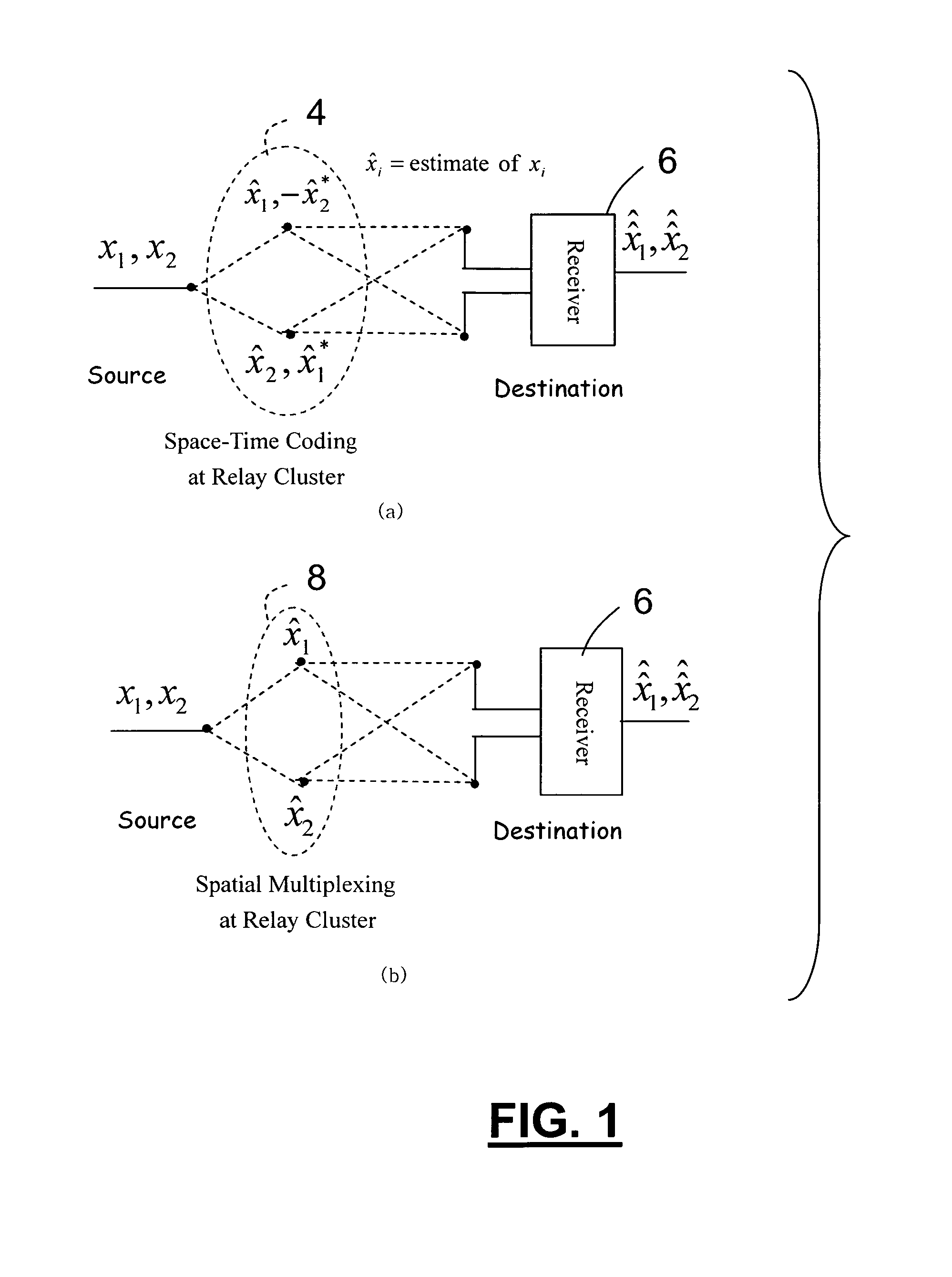
[0047]The present invention provides for a method and system for cooperative spatial multiplexing scheme. This method provides a form of multiplexing. Generally, multiplexing is the process of mixing multiple signals for transmission through a single channel. Here, the multiplexing is space-division multiplexing or spatial multiplexing. The channel is shared by concentrating individual signals in non-overlapping narrow beams. Spatial multiplexing splits a si...


PUM


Abstract

A cooperative spatial multiplexing scheme in which the transmitter (source), equipped with a single antenna, forms virtual antenna arrays from a collection of distributed antennas belonging to different wireless terminals, and transmit a high-rate data stream to those terminals (relays). Each relay detects only a subset (called sub-stream) of the data stream and all relays forward their sub-streams simultaneously over the same physical channel. Then the receiver (destination) nulls and cancels the interference from different relays in order of the magnitude of log-likelihood ratio and detects the signal transmitted from the source.

Description

CROSS-REFERENCE TO RELATED APPLICATIONS[0001]This application claims priority under 35 U.S.C. §119 of a provisional application Ser. No. 60 / 672,757 filed Apr. 19, 2005, which application is hereby incorporated by reference in its entirety.BACKGROUND OF THE INVENTION[0002]The present invention relates to wireless communications and more particularly to cooperative communications. Future wireless communication environments are highly resource-constrained, offering a limited and tightly regulated spectrum. The energy supply on wireless terminals is usually limited, and, in many scenarios they must operate for many years without battery replacement. A promising approach to overcome such limitations is the use of multiple antennas both to transmit and receive information, which can provide a diversity gain as well as a multiplexing gain at no extra bandwidth or power consumption [1]-[7]. Although attractive, this option requires collocated antenna elements with antenna spacing of tens of...

Claims


Application Information

Patent Timeline
IPC IPC(8): H04L12/28
CPCH04L12/28H04B7/026H04B7/15592
Inventor KIM, SANG WU
Owner IOWA STATE UNIV RES FOUND
Why Eureka
Try Eureka