Solids distributor for injection plants, blast furnaces and the like

a distributor and injection plant technology, applied in the direction of combustion process, blast furnace, lighting and heating apparatus, etc., can solve the problems of not being able to ensure the compensation required, no longer being compensated,

Active Publication Date: 2013-01-08
CLAUDIUS PETERS PROJECTS
View PDF28 Cites 13 Cited by
  • Summary
  • Abstract
  • Description
  • Claims
  • Application Information

AI Technical Summary

Benefits of technology

[0019]The invention extends, further, to a distributor head as described herein. It is suitable particularly for building under ex

Problems solved by technology

These inhomogeneities are so great and have such dynamics that they can often no longer be compensated by means of the individual controls used according to the prior art on t

Method used


Image

  • Solids distributor for injection plants, blast furnaces and the like
  • Solids distributor for injection plants, blast furnaces and the like
  • Solids distributor for injection plants, blast furnaces and the like

Examples


Embodiment Construction

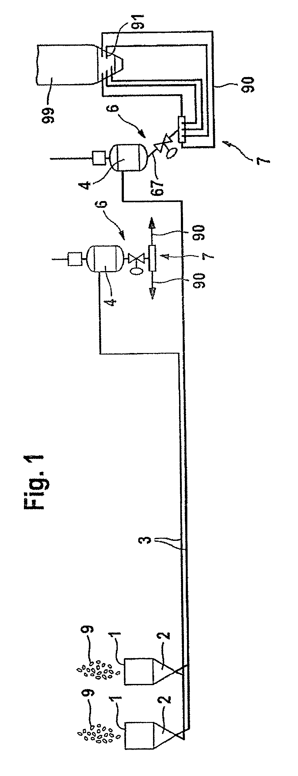
[0024]The invention is explained by the example of a plant which supplies ground coal as solid fuel to a blast furnace. The plant, illustrated in FIG. 1, for the supply of pulverized coal is of double-flow design. This means that two parallel strings are provided, which are constructed identically to one another. Only one string is therefore described in more detail below; the statements apply correspondingly to the other string.

[0025]Coal 9 is supplied from above to a conveying plant 2 via a feed port 1. The conveying plant may be designed as a twin pressure vessel plant known per se.

[0026]The ground coal passes into a supply line 3, by means of which it is supplied to a coal distributor 6 at a blast furnace 99 (illustrated for only one string). The line 3 may have a considerable length, distances of several hundred meters up to one kilometer being possible.

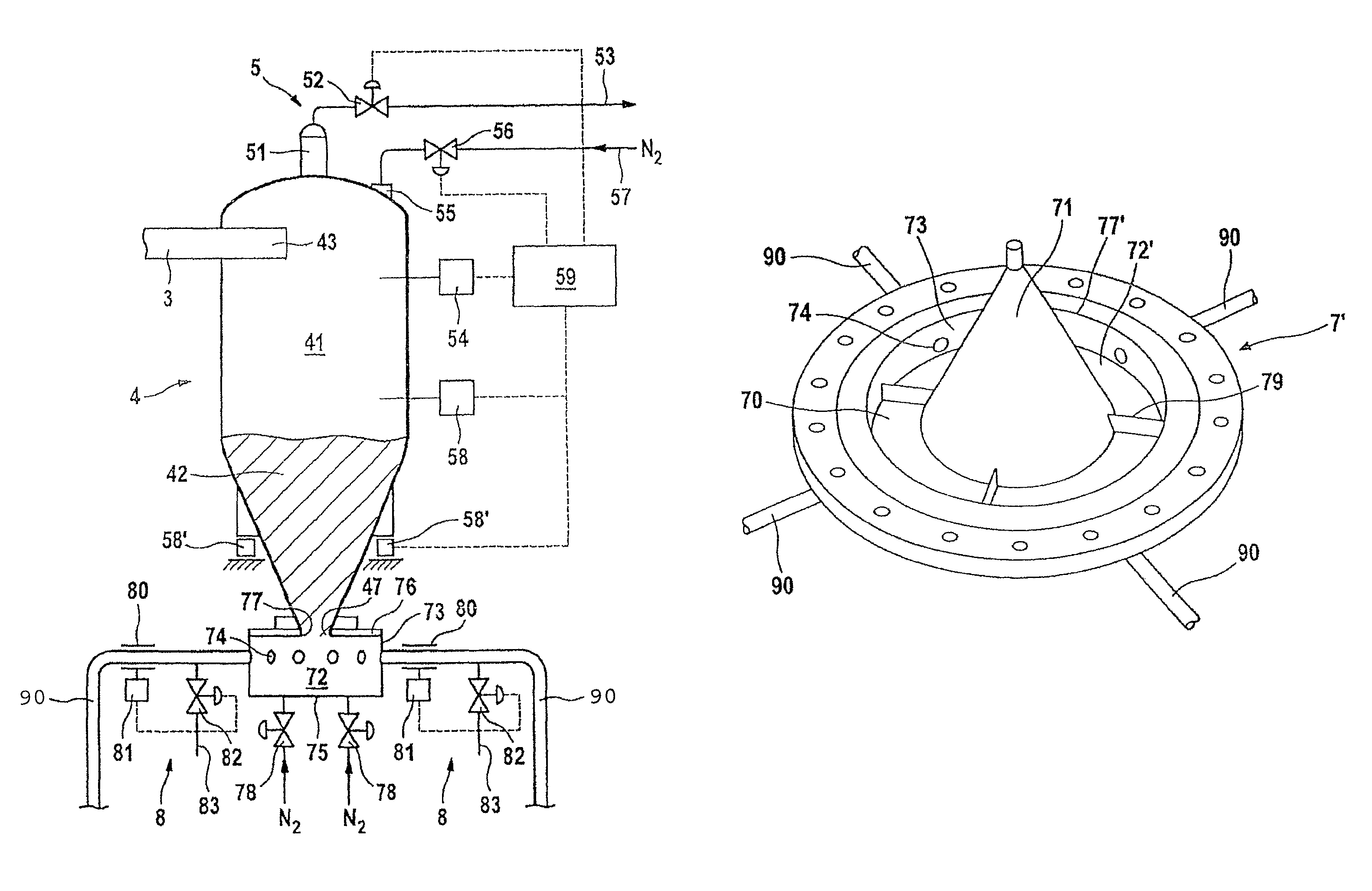
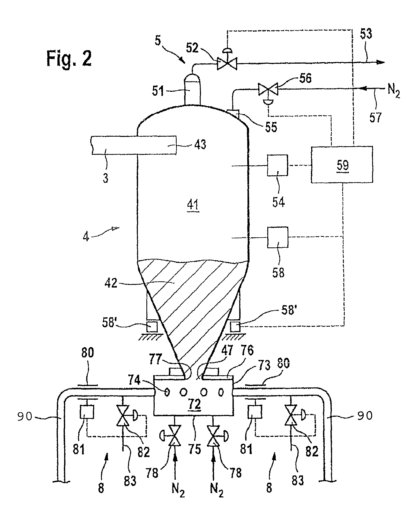
[0027]The supply line 3 issues in the upper region, designed as a gas space 41, of a pressure vessel 4 of the coal distributor...


PUM

PropertyMeasurementUnit
Pressureaaaaaaaaaa
Heightaaaaaaaaaa
Contraction enthalpyaaaaaaaaaa

Abstract

A solids distributor for injection plants includes a collecting chamber having a plurality of lance lines leading away from the chamber. The chamber has a supply connection for a solid to be distributed and is surrounded by a common wall in which a plurality of ports is formed. The lance lines are connected to the ports, and an annular gap is formed in front of the ports and along the common wall. A pressure vessel is arranged geodetically above the collecting chamber, the lower part of the pressure vessel being designed as a bunker, having an outlet providing a direct and continuous junction to the supply connection and an upper part designed as a gas space. The collecting chamber may include a central displacement body which forms the annular gap with the common wall and which may be an upwardly tapering cone which projects out of the collecting chamber.

Description

REFERENCE TO RELATED APPLICATION[0001]This application is the national stage under 35 USC 371 of International Application No. PCT / EP2007 / 009131, filed Oct. 22, 2007, which claims the priority of German Patent Application No. 20 2006 016 093.0, filed Oct. 20, 2006, the entire contents of which are incorporated herein by reference.FIELD OF THE INVENTION[0002]The invention relates to a solids distributor for injection plants, in particular for blast furnaces, with a chamber and with a plurality of lance lines leading away, the chamber having a supply connection for a solid, such as ground coal, which is to be distributed. The invention relates, further, to a distributor head for such a solids distributor.BACKGROUND OF THE INVENTION[0003]For the heating of blast furnaces, burners in power stations and similar apparatus, ground solid fuel, in particular coal, is increasingly used as fuel. This affords the advantage that, as compared with the combustible material conventionally used, suc...

Claims


Application Information

Patent Timeline
IPC IPC(8): B65G53/40
CPCF23K3/02F23K3/06F27B1/10C21B5/003
Inventor HILGRAF, PETERSCHUMPE, DIETRICHNOLDE, HANS-DIETERGOECKE, VOLKER
Owner CLAUDIUS PETERS PROJECTS
Why Eureka
Try Eureka