3D motion detection and correction by object tracking in ultrasound images

a technology of object tracking and motion detection, applied in the field of ultrasound imaging, to achieve the effect of increasing the precision of determined motion, acceleration and/or ankle information, and increasing the accuracy of determined motion

Inactive Publication Date: 2013-01-08
MEDIRI
View PDF20 Cites 9 Cited by
  • Summary
  • Abstract
  • Description
  • Claims
  • Application Information

AI Technical Summary

Benefits of technology

[0032]A preferred arrangement comprises more than one ultrasound transducer to simultaneously or nearly simultaneously view a structure of interest from different perspectives and positions. Due to the “multi-view” dataset provided by more than one ultrasound transducer objects which are in motion can be continuously examined without leaving the viewing window of the ultrasound transducers. By arranging the more than one ultrasound transducers in such a way that they provide redundant sound windows, hyper- or hypo-dense structures (e.g. bones or air) can be obviated from obscuring the sound window. The “multi-view” dataset also enables the acquisition of vital parameters (e.g. motion) that span a three-dimensional space even with ultrasound transducers of lower data-dimensionality (i.e. ultrasound transducers with one-dimensional or two-dimensional data acquisition capabilities) In this way it is possible to retrieve three-dimensional information of the time evolution of the object using multiple transducers with two-dimensional or one-dimensional data acquisition capabilities.
[0040]Any information about the object of interest which is a-priori known may be encoded by the one or more reference models and gained from the one or more reference models by the processing unit. The one or more reference models can be parametrizable: Certain parameters of the models are variable. Several of the variable parameters (specifiable parameters) can be defined by the processing unit, whilst the values of the remainder of the variable parameters are calculated depending on the actual value of the specifiable parameters. To match the set of one or more reference models to a frame of ultrasound data provided by the ultrasound unit the processing unit defines the specifiable parameters in such a manner that their values resemble corresponding data from the frame of ultrasound data. By using the one or more reference models, information can be provided by the processing unit which is not enclosed by the ultrasound data. E.g. ultrasound data coming from multiple transducers of lower data-dimensionality can be used to fit the model—which then provides full three-dimensional information. This means that the acquisition of sparse ultrasound data is sufficient to gain three-dimensional information about vital parameters. This significantly accelerates the data acquisition process and reduces the time for parameter calculation so that the retrieval of three-dimensional information is possible in real-time.
[0046]In a further preferred embodiment, the weights for calculating the weighted average for each set within the sequence of several sets of one or more reference models is propagated by a autoregressive model: The weights for calculating the weighted average of the one or more reference models of a first set from the sequence of several sets of one or more reference models are propagated by the processing unit to calculate the weighted average of the one or more reference models of a second set from the sequence of several sets of one or more reference models. The first set is matched to a first frame of ultrasound data and the second set is matched to a second frame of ultrasound data, wherein the second frame of ultrasound data is acquired by the one or more ultrasound transducers subsequently to the first frame of ultrasound data. Building sets of one or more reference models based on preceding sets of one or more reference models and propagating the weights for calculating the weighted averages increases the robustness against clutter and noise within the ultrasound data.
[0053]In a second preferred embodiment, at least one of the position sensors is a motion, acceleration and / or ankle sensor to determine motion, acceleration and / or ankle information of the one or more ultrasound transducers which are attached with one of the at least one motion, acceleration and / or ankle sensors. Electromagnetically non-transparent sensors and motion, acceleration and / or ankle sensor can be applied simultaneously, meaning that at least one of the position sensors is electromagnetically non-transparent and at least one of the position sensors is a motion, acceleration and / or ankle sensor. This increases the precision of the determined motion, acceleration and / or ankle information of the one or more ultrasound transducers.
[0054]In another preferred embodiment, the position detection system comprises one or more optical cameras to determine the position and / or orientation of each of the one or more ultrasound transducers. These optical cameras record the one or more ultrasound transducers. The position and / or orientation of each of the one or more ultrasound transducers can be determined by means of object recognition methods or by means of markers attached to the one or more ultrasound transducers. Preferably, the optical cameras and the position sensors can be applied simultaneously, meaning that the position detection system comprises one or more optical cameras and one or more position sensors, such as electromagnetically non-transparent sensors, motion, acceleration and / or ankle sensors, wherein each of the on or more position sensors is attached to one of the one or more ultrasound transducers. This increases the precision of the determined motion, acceleration and / or ankle information of the one or more ultrasound transducers.

Problems solved by technology

However, all of theses methods suffer from the disadvantage that they do not observe the motion itself but use a very indirect correlate.
Hence, they crucially have to rely on a reproducible positioning of structures during several breathing phases and are not able to control the actual position of the object of interest.
This significantly prolongs the therapy and very much reduces its time efficiency.
However, the conclusion from such external motion information to displacements of internal organs is not easily possible since these are often—if at all—not very well correlated.
However, since these methods rely on ionizing radiation they add dose to the patients treatment plan and cannot be performed in real-time without seriously harming the patient.
The inherently low soft-tissue contrast of x-rays also limits the usability of these methods to dense structure matching, so that often the implantation of internal markers in an invasive procedure is necessary.
These limitations largely restrict the application of x-ray methods to the research environment or special patient groups.
In particular, it cannot be applied to detect and compensate organ motion.
Since this method determines the organ motion in an indirect way the results are not sufficiently precise.
However, besides the fact that it does not give a feasible solution for structure tracking on ultrasound images (Only a very basic correlation method is suggested which appears be slow and not robust enough for ultrasound tracking.) it only uses a single 2D ultrasound transducer on a fixed bracket.
In such a single-view approach moving structures of interest tend to leave the viewing window of the ultrasound transducer and cannot be continuously examined.
Due to the fixed clamp the transducer can easily loose contact with the patient.
The 2D technique can only measure object displacements within the ultrasound plane and hence is not suited for online-monitoring of organ motion in 3D.
Devices with a single 3D ultrasound transducer cannot be used to realize object tracking feasible for clinical application.
Similar to arrangements with two-dimensional transducers described above, for single view 3D methods the risk of loosing or masking structures remains.
3D datasets are very large in size.
The huge amount of data impedes the application of effective tracking methods, Electronically swept 3D transducers are very expensive and quite massive.
Hence, those transducers are not real-time capable.
Like electronically swept transducers, mechanical transducers are furthermore quite massive, so they have to be mounted on a fixed clamp with the risk of loosing contact to the patient.
Embodiments according to the current artlimit the duration of a radiation exposure,cause idle time of the accelerator,lack of precision,harm the patient due to additionally required doses of radiation,are not able to observe motion directly but have to use indirect correlatescannot detect soft-tissue with a sufficiently high contrasttend to loose contact to the patient's body,are too expensive for clinical use,cannot retrieve tree-dimensional data,are deranged by hyper- or hypo-dense structuresloose sight of objects, if they move, and / orcannot provide data in real-time.
Currently, no system exists which is able to directly monitor vital parameters and / or tissue motion inside a patient during radiation therapy to control motion in real-time.

Method used


Image

  • 3D motion detection and correction by object tracking in ultrasound images
  • 3D motion detection and correction by object tracking in ultrasound images
  • 3D motion detection and correction by object tracking in ultrasound images

Examples


Embodiment Construction

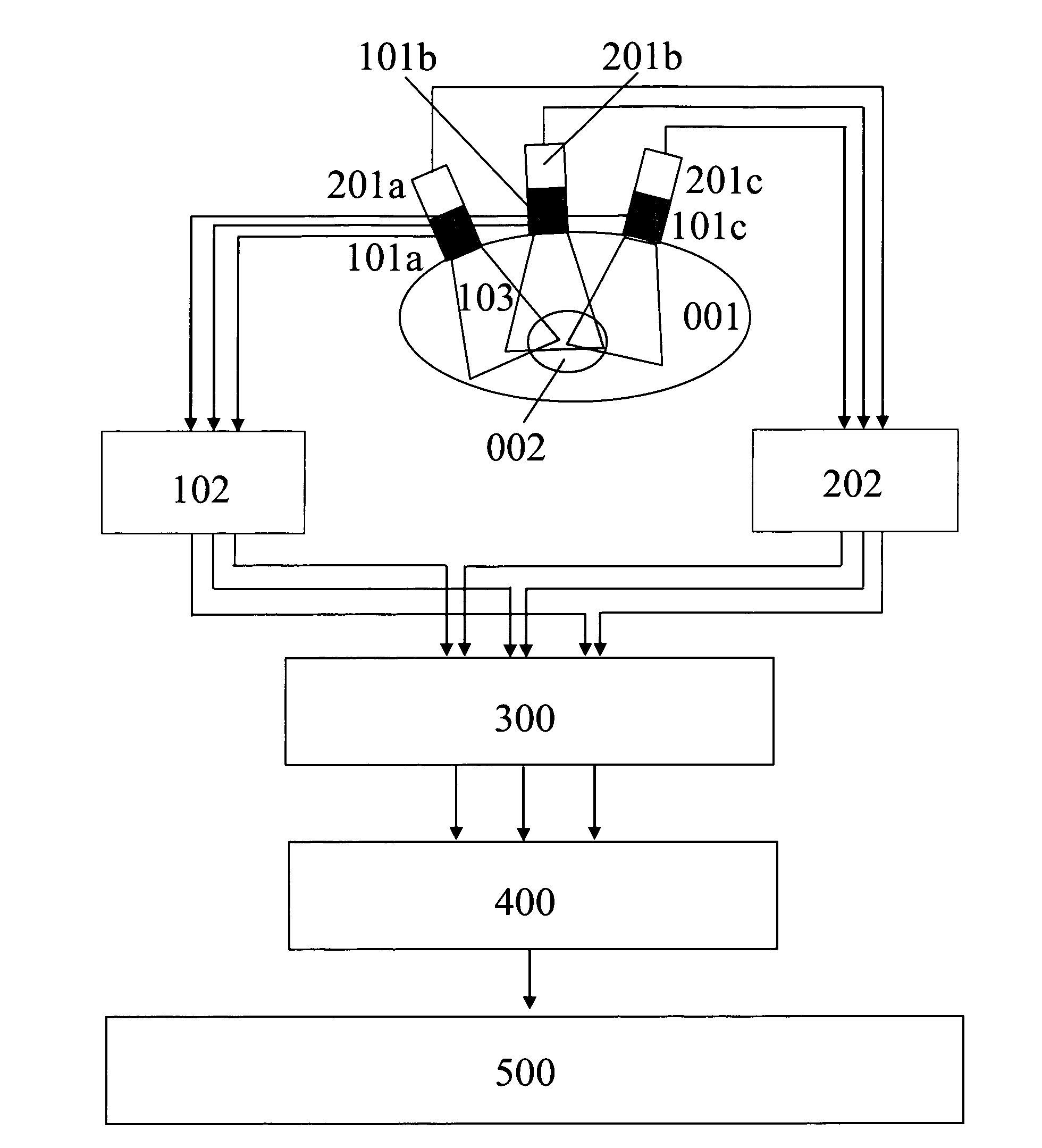
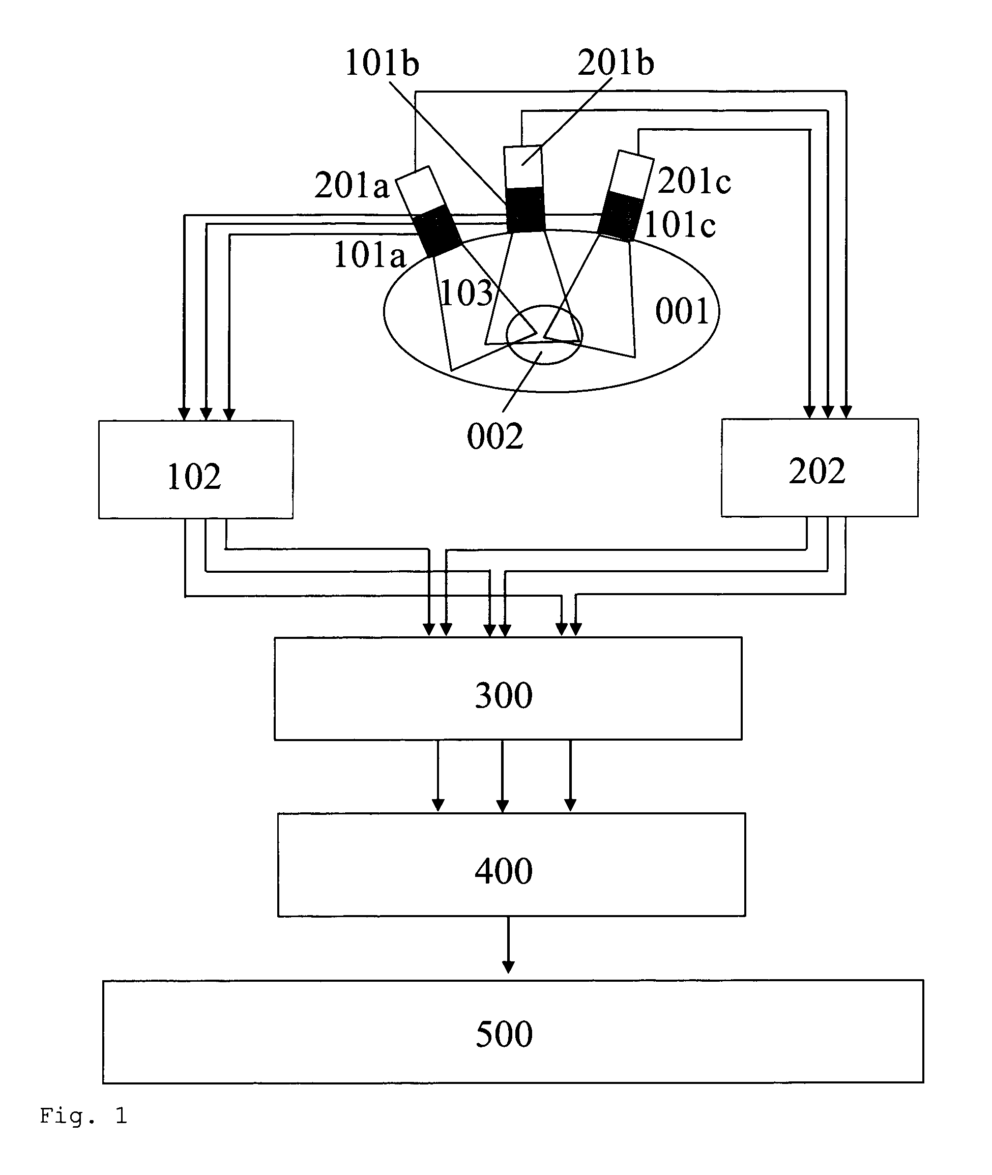
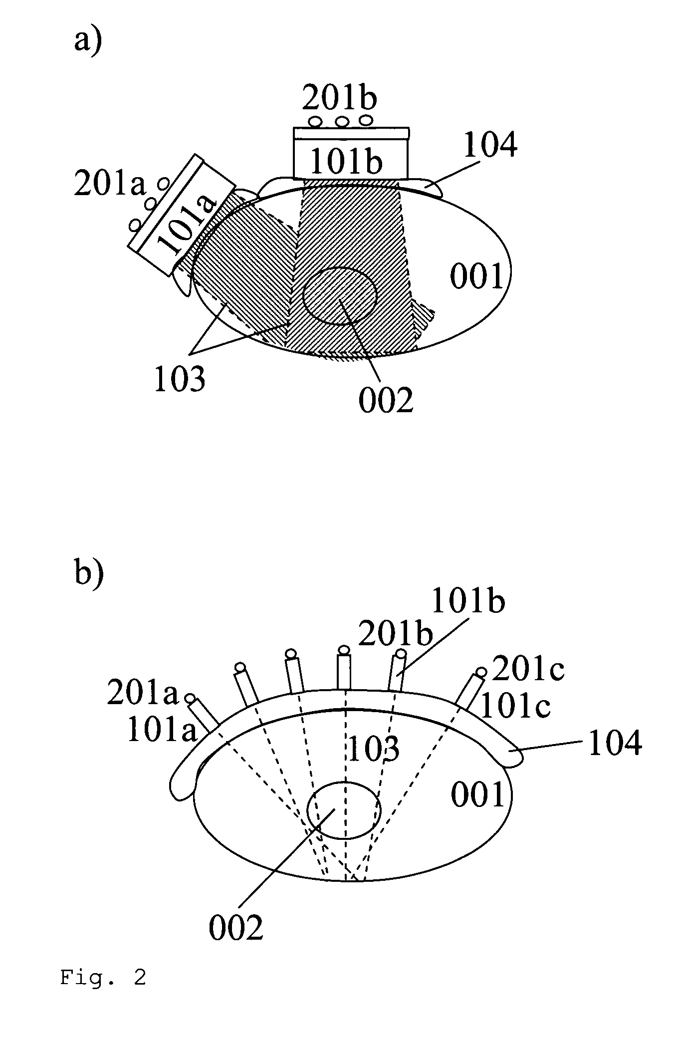
[0078]As delineated in FIG. 1, a preferred embodiment of the claimed invention comprises the following components:[0079]a) an ultrasound unit 102 (including a transmit and receive unit) providing structural and / or physiologic data in real-time;[0080]b) one or more one 1D (one-dimensional), 2D (two-dimensional) or 3D (three-dimensional) ultrasound transducers 101a, 101b, 101c coupled to the ultrasound unit 102 to provide linearly independent (i.e. acquired from different directions, in multiple non-coplanar planes or non-collinear lines) sparse or complete 3D ultrasound data. The ultrasound transducers 101a, 101b, 101c can be pasted directly to the body 001 or be mounted to the body 001 in a different way. Furthermore, they can be either fixed with respect to the reference frame or float freely;[0081]c) a system 201a, 201b, 201c, 202 to continuously determine the localization and viewing direction of each ultrasound transducer 101a, 101b, 101c relative to a fixed frame of reference;[...


PUM


Abstract

An arrangement to determine physiologic data, position, orientation and / or geometry of an object of interest includes an ultrasound unit with a multiplicity of ultrasound transducers to monitor physiologic parameters, especially motion and deformation, of an object of interest encapsulated by a body in real-time in three dimensions of space and to generate numerical control or trigger information for other medical devices.

Description

[0001]This patent application is a U.S. national stage application of PCT international application PCT / EP2009 / 004678 filed on 29 Jun. 2009 and claims priority of PCT / EP2008 / 008303 filed on 30 Sep. 2008.FIELD OF THE INVENTION[0002]The present invention generally relates to the field of ultrasound imaging. In particular, it relates to an arrangement comprising an ultrasound system to determine physiologic data, position, orientation and / or geometry information of an object of interest in 3D using sparse 3D data acquired from a multiplicity of ultrasound transducers in real-time in order to control other medical devices.BACKGROUND OF THE INVENTION[0003]In many medical applications such as medical imaging and radiation therapy the quality of the outcomes is significantly impaired by patient and organ motion. Especially in abdominal radiation therapy patient and organ movement is a crucial factor.[0004]The accuracy of current radiation methods lies well within the millimeter range. Howe...

Claims


Application Information

Patent Timeline
Patent Type & Authority Patents(United States)
IPC IPC(8): A61B8/00
CPCA61B8/08A61B8/4245A61B8/4254A61B8/483A61B8/5276A61B8/0833A61B19/5244A61B2019/5248A61B2019/5251A61B2019/5255A61B2019/5265A61B2034/2048A61B2034/2055A61B34/20A61B2034/2051A61B2034/2065
Inventor GUNTHER, JORG MATTHIASBONGERS, ANDRE
Owner MEDIRI
Why Eureka
Try Eureka