Single-sided dynamic spine plates

a spine plate and single-sided technology, applied in the field of spine plates for internal fixation, can solve the problem that prior art spine plates cannot accommodate stabilization

Active Publication Date: 2013-01-08
LIFE SPINE INC
View PDF113 Cites 17 Cited by
  • Summary
  • Abstract
  • Description
  • Claims
  • Application Information

AI Technical Summary

Problems solved by technology

As such, these prior art spine plates cannot accommodate stabilization situations wherein it is desired to provide a spine plate on lateral sides of the vertebrae or in other situations where a smaller width spine plate is appropriate.

Method used


Image

  • Single-sided dynamic spine plates
  • Single-sided dynamic spine plates
  • Single-sided dynamic spine plates

Examples


Embodiment Construction

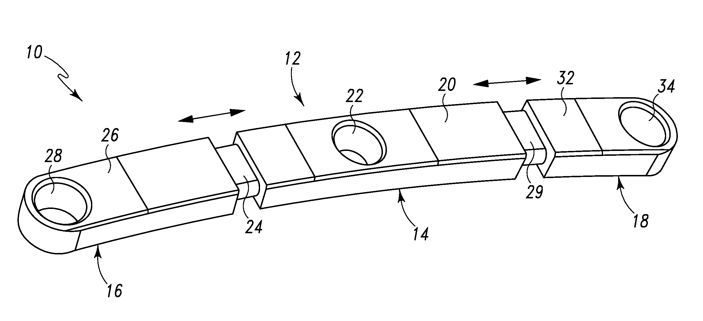
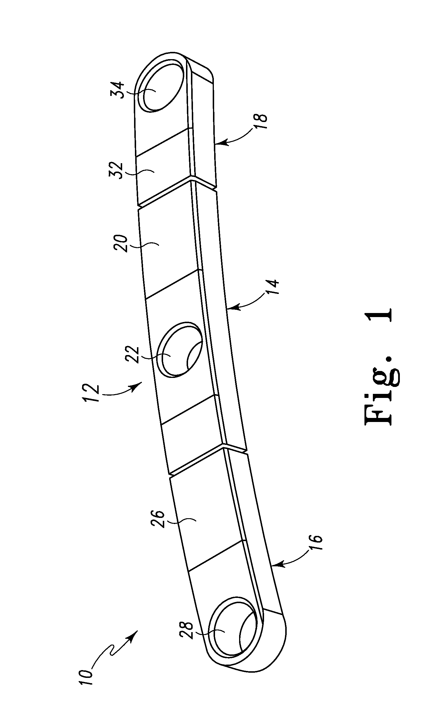
[0042]Referring to the figures and particularly to FIGS. 1-7, there is depicted an embodiment of a single sided dynamic spine plate generally designated 10. The single sided dynamic spine plate 10 is formed of a suitable biocompatible material (“biomaterial”) such as, for example, titanium, stainless steel, an alloy or the like. The single sided dynamic spine plate 10 (spine plate 10) is characterized by a multi-component body 12 fashioned as an elongated rectangle. The spine plate 10 is shown as a two level (2-L) spine plate but may be fashioned as a single level (1-L) to a multi-level or n-level (n-L) spine plate in accordance with the present principles.

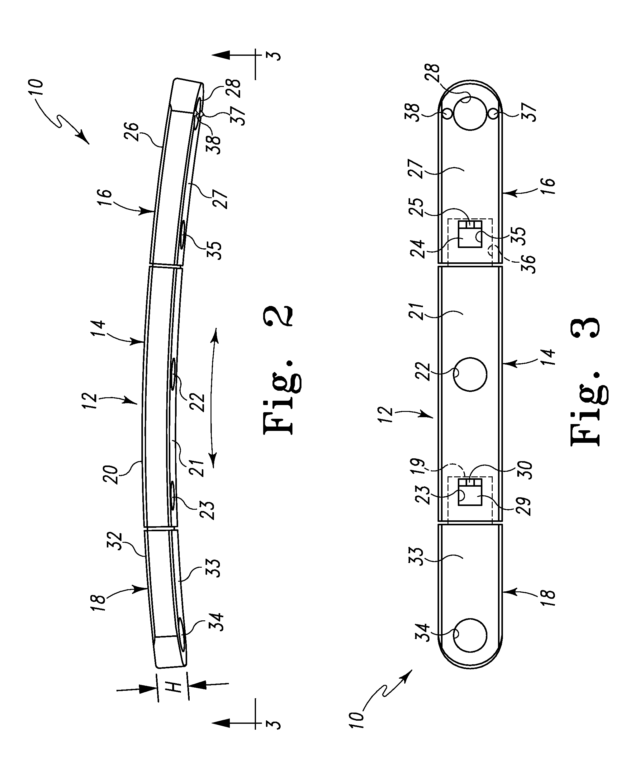
[0043]The body 12 is formed from a plurality of components and, in the embodiment shown in the figures, is formed of three components; a middle component, portion or section 14, a first end component, portion or section 16, and a second end component, portion or section 18. The body 12 defines a height or profile “H” (see, e.g. FI...


PUM


Abstract

A dynamic spine plate is formed with only a single row of bone screw bores that extend along a generally superior / inferior axis of the spine plate, providing a single-sided dynamic spine plate. The single-sided dynamic spine plate is formed from a plurality of spine plate components that are coupled dynamically to one another. This provides a modular, single-sided dynamic spine plate. The spine plate components are coupled dynamically to one another via socket and projection interfaces, the socket and projections interfaces incorporating resilient coupling and retention structures that allow limited movement of the spine plate components relative to one another. This provides for dynamic extension of the spine plate components relative to one another. The resilient coupling structure connects the spine plate components, providing a self-biased, snap fit coupling of spine plate components. Rotation stabilizers may be provide on the present single-sided dynamic spine plate that provide rotational stability to the spine plate in addition to the bone screws that will attach the spine plate to the vertebrae.

Description

RELATED APPLICATIONS[0001]This patent application claims the benefit of and / or priority to U.S. Provisional Patent Application Ser. No. 61 / 092,836 filed Aug. 29, 2008, entitled “Single Sided Dynamic Spine Plate” the entire contents of which is specifically incorporated herein by this reference.BACKGROUND OF THE INVENTION[0002]1. Field of the Invention[0003]The present invention relates generally to devices for the internal fixation of the spine particularly within the fields of orthopedics and / or neurosurgery such as spinal implants for holding vertebral bones fixed relative to one another and, more particularly, to dynamic bone fixation implants for use in spinal surgical procedures for stabilizing the relative motion of vertebrae by temporarily or permanently immobilizing vertebrae of the spine.[0004]2. Background Information[0005]Spine plates have been used for many years to increase spine stability following single and multi-level spine surgery. Particularly, spine plates implan...

Claims


Application Information

Patent Timeline
Patent Type & Authority Patents(United States)
IPC IPC(8): A61B17/70
CPCA61B17/7059A61B17/8023
Inventor BUTLER, MICHAEL S.HARTSELL, BRIAN D.
Owner LIFE SPINE INC
Why Eureka
Try Eureka