A device for bone support with improved rotational stability

a technology of rotational stability and bone support, which is applied in the direction of osteosynthesis devices, internal osteosynthesis, internal osteosynthesis, etc., can solve the problems of not preventing any dynamisation of fractures, and achieve the effects of improving healing fractures, preventing any dynamisation of fractures, and improving the rotational stability of proximal fracture fragments

Active Publication Date: 2016-09-08
GENERAL SURGICAL COMPANY INDIA PVT
View PDF7 Cites 10 Cited by
  • Summary
  • Abstract
  • Description
  • Claims
  • Application Information

AI Technical Summary

Benefits of technology

[0011]The object of the present invention is to provide an implant comprising of individual elements for bone support in the form of an elongated hollow rod commonly referred to as intermedullary ‘nail’ with increased rotational stability of the fracture fragment around the hip area than devices in the prior art.
[0012]It is a further object of the present invention to provide an intermedullary device that can also fix intracapsular fracture. Yet another feature of this invention is to provide a bone support which is easy to manufacture. Yet another objective is to implant the device easily and percutaneous. It is also a further object of the present invention to provide a hip screw that can be easily removed without damaging the surrounding bone. It is also a further object of the present invention to be able to insert the device using the same targeting device used by the hip screw.BRIEF DESCRIPTION OF THE INVENTION

Problems solved by technology

This will not prevent any dynamisation of the fracture.

Method used


Image

  • A device for bone support with improved rotational stability
  • A device for bone support with improved rotational stability
  • A device for bone support with improved rotational stability

Examples


Embodiment Construction

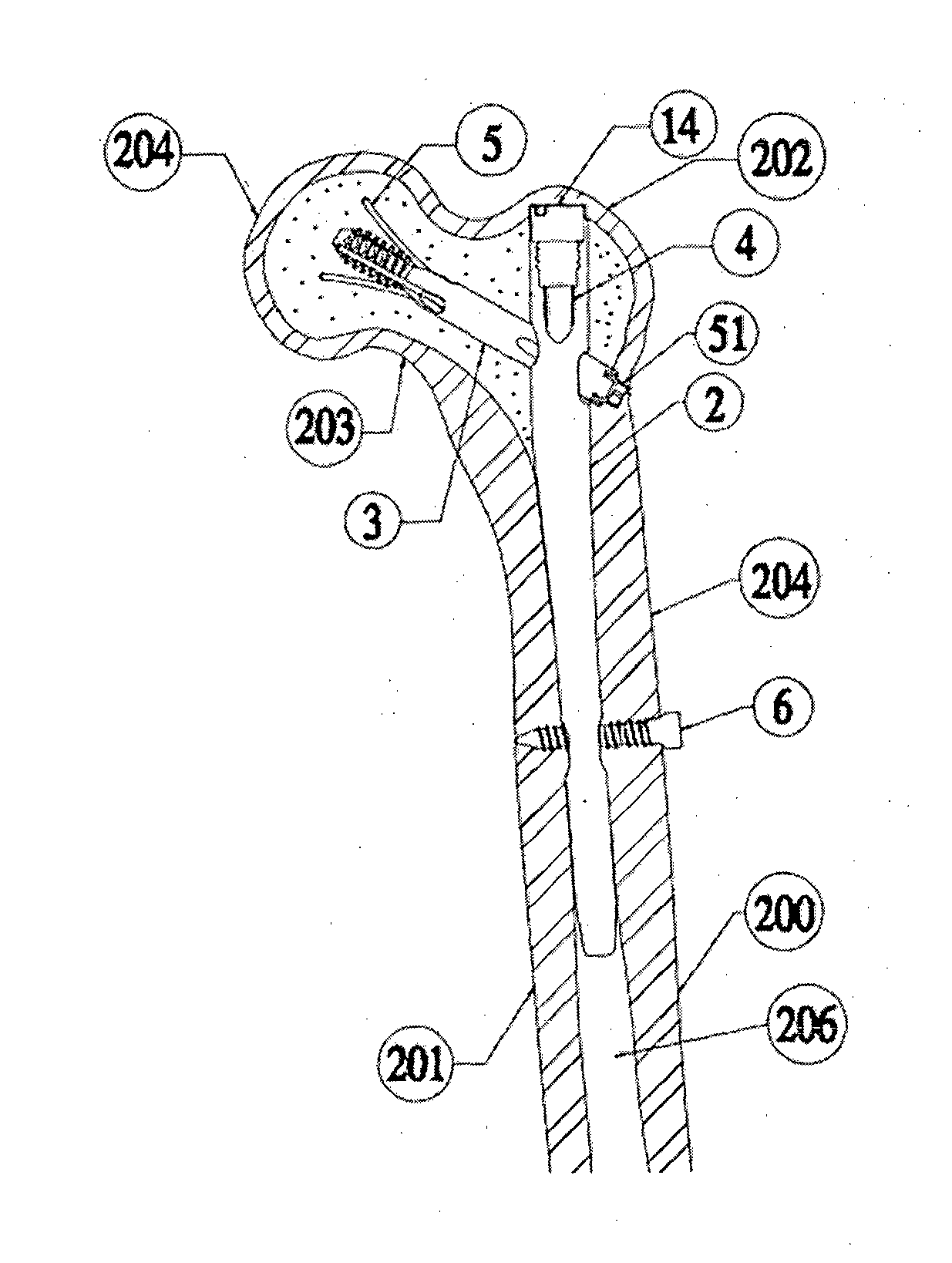
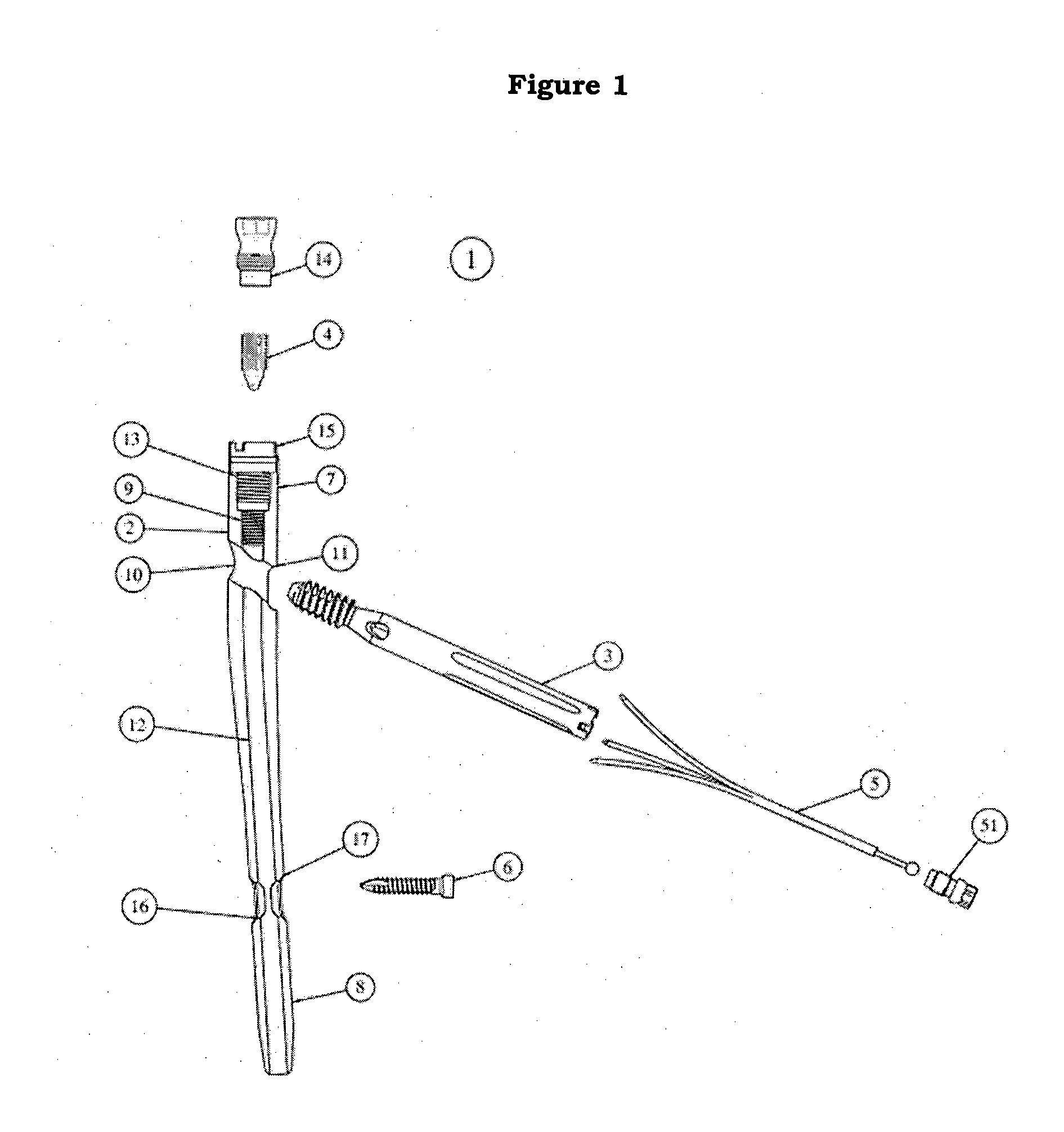
[0019]An implant or a fixating device with a smoothly curved rod closely fitting the internal geometry of the upper femoral shaft which can be inserted into the medullary canal of the intact femur making it suitable for fixing all fractures which may be encountered in the neck, trochanteric or subtrochanteric regions of the femur. This device can also fix intracapsular fractures. The said implant can be inserted through two small incisions which do not cut muscle significantly or disturb the fracture haemotoma.

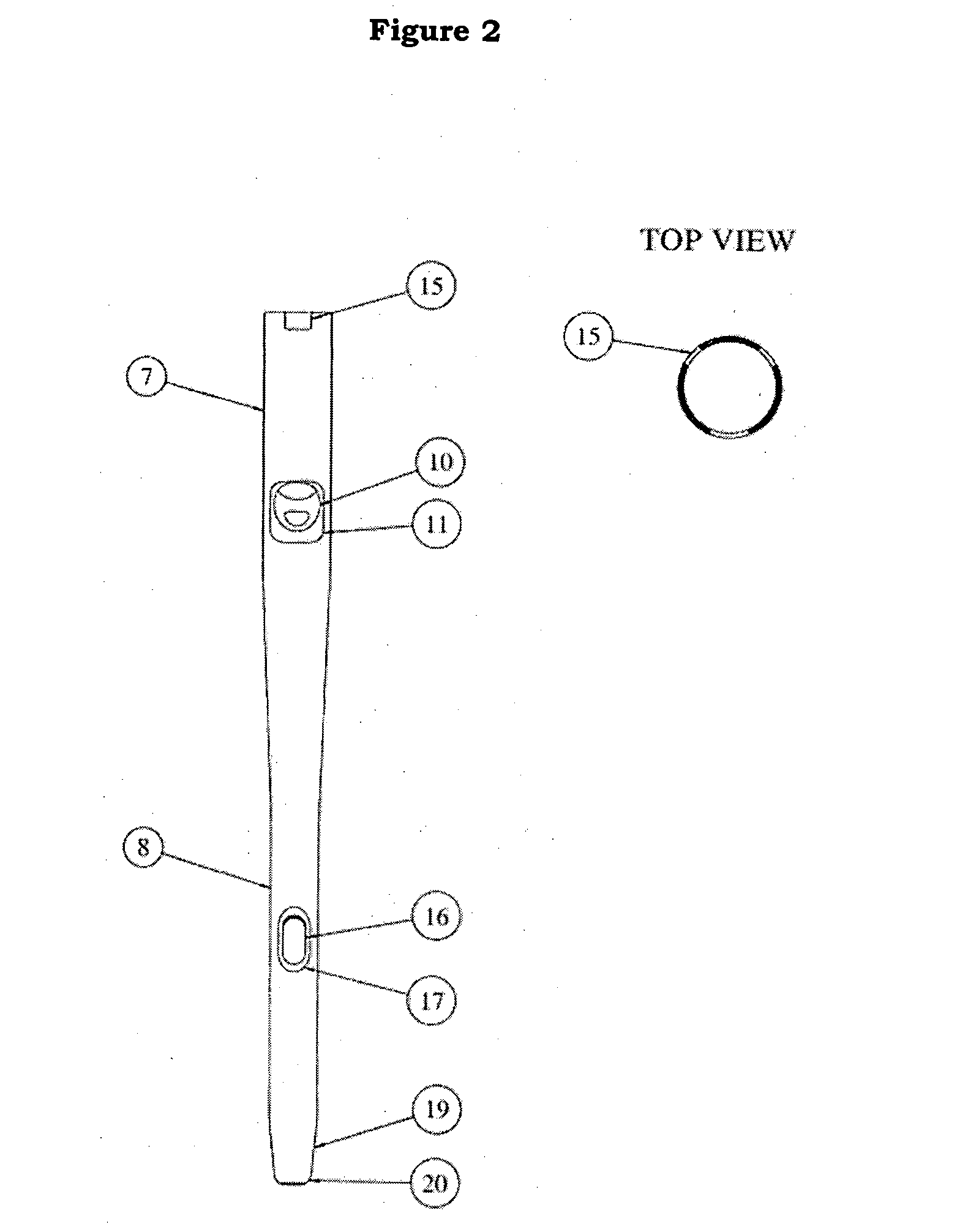
[0020]The said device with a longitudinally slotted hip screw which permits operative compression of the fracture and holds this compression yet allows sliding as further compression of the fracture occurs under forces of weight bearing. This device comprises of a hollow cylindrical shaft with a screw portion at its upper proximal end and four equally spaced longitudinal grooves at its lower distal end. Between these ends are three equally distant angled holes through which th...


PUM


Abstract

A bone support fixating device with a longitudinally slotted hip screw which permits operative compression of the fracture and holds this compression yet allows sliding as further compression of the fracture occurs under forces of weight bearing; comprising a hollow cylindrical shaft with a screw portion at its upper proximal end and four equally spaced longitudinal grooves at its lower distal end, having three equally distant angled holes between the ends, through which three wires can be inserted, the three ‘elastic’ proximally curved wires, welded, glued or crimped distally, can be inserted into the hip screw collectively called the ‘tri-wire’; The proximal end has the wires curved outward, with all three wires equally spaced; upon pushing the tri-wire into the hip screw, the wires goes through the angle holes in the hip screw and provides three projections equally spaced; which improves the rotational stability of the proximal fracture fragment.

Description

FIELD OF THE INVENTION[0001]The present invention particularly relates to an implant comprising of individual elements for the fixation of fractures of the femoral neck, trochanteric and subtrochanteric regions of the femur with improved rotational stability.BACKGROUND OF THE INVENTION[0002]Devices for fixing a femur facture in the vicinity of the hip joint are already known.[0003]There are various devices in the market that can be used to fix fractures near the hip. These devices over the years have had several iterations so as to try to improve the rotational stability of the hip fracture. Some of the nail designs include incorporating two hip screws instead of one, reamer like threads on the screw and augmentation of cement. Augmenting cement has the disadvantage that it's almost impossible to remove the hip screw if required without damaging the hip. The current designs in the market suffer from disadvantages, the major being that they have not been proved to improve rotational ...

Claims


Application Information

Patent Timeline
Patent Type & Authority Applications(United States)
IPC IPC(8): A61B17/72
CPCA61B17/725A61B17/7266A61B17/7283A61B17/744
Inventor HALDER, SUBHASH CHANDRA
Owner GENERAL SURGICAL COMPANY INDIA PVT
Why Eureka
Try Eureka