Rotating blade and stationary blade combined self-adaption adjustment multistage axial flow gas compressor

A technology of axial flow compressor and combined adjustment, which is applied in axial flow pumps, mechanical equipment, machines/engines, etc., and can solve problems such as complex vortex structure, complex flow, and small flow space

Active Publication Date: 2017-09-15
BEIHANG UNIV
View PDF7 Cites 10 Cited by
  • Summary
  • Abstract
  • Description
  • Claims
  • Application Information

AI Technical Summary

Problems solved by technology

[0002] The compressor is the core component of the aviation gas turbine engine. It is composed of multi-stage rotors and stators arranged in a staggered order. Its function is to increase the gas pressure rise; in the flow inside the compressor, due to the small flow space, the reverse pressure of the fluid The gradient effect is strong, and it has a complex vortex structure; the corner separation structure located at the stator end zone and the leakage flow structure located at the rotor tip are the main secondary flow structures inside the compressor, and are the main causes of flow loss and blockage inside the compressor. The source has a vital impact on the performance of the compressor's pressure ratio, efficiency, and margin. In severe cases, it will cause the stall and surge of the compressor, which will bring disastrous consequences; after decades of research, many scientific research works Researchers have had a deep understanding of the corner separation flow and tip leakage flow of the compressor, but due to the limitation of space and the complexity of the flow, it has not been well realized according to the existing research results. Effective control of the flow in the machine; especially by making full use of the characteristics of step-by-step pressurization of the flow in the compressor, through a certain self-circulation adjustment mechanism, while using and improving the flow structure that is not conducive to performance, to achieve the purpose of improving the performance of the compressor
[0003] For the rotor-stator end zone of the compressor, the flow congestion caused by the separation / stall of the three-dimensional angular zone makes the performance of the compressor drop sharply; Larger and wider effective working range; however, with the increase of compressor load, the degree of three-dimensional angular separation increases sharply, and the range of effective working angle of attack decreases sharply; at present, the three-dimensional angular separation and stall The flow control technology in the field can be divided into two categories: active control technology and passive control technology in terms of whether additional energy is introduced: active control technology mainly includes plasma excitation, boundary layer blowing and suction technology, synthetic jet, etc.; passive control technology mainly includes Vortex generators, wing knives, end wall shapes, etc.; the boundary layer suction technology in the active control technology has the characteristics of a wide range of applications and obvious benefits, but it requires additional energy and is not easy to implement in engineering; the existing traditional passive control technology , not self-adaptive, and the range of effective working conditions is often limited, failing to solve the problem of corner separation of the next generation of high-load compressors in engineering
[0004] For the compressor rotor tip, the tip leakage flow has an important influence on the stable working state of the compressor. The overflow of the leading edge of the rotor tip and the reverse flow of the trailing edge are the two precursors of the stall of the compressor. Reasonable introduction of the jet at the tip of the rotor can effectively improve the leakage flow of the rotor tip, increase the stall margin of the rotor, and achieve a better stability expansion effect; the traditional air blowing technology of the rotor tip is mostly active control, which requires additional energy to be introduced. Conducive to engineering realization; there is also a scheme of using a self-circulating casing, but its jet outlets are distributed in an intermittent array along the circumferential direction, which cannot form a uniform jet flow in the circumferential direction, which interferes with the rotation stability

Method used


Image

  • Rotating blade and stationary blade combined self-adaption adjustment multistage axial flow gas compressor
  • Rotating blade and stationary blade combined self-adaption adjustment multistage axial flow gas compressor
  • Rotating blade and stationary blade combined self-adaption adjustment multistage axial flow gas compressor

Examples


Embodiment 1

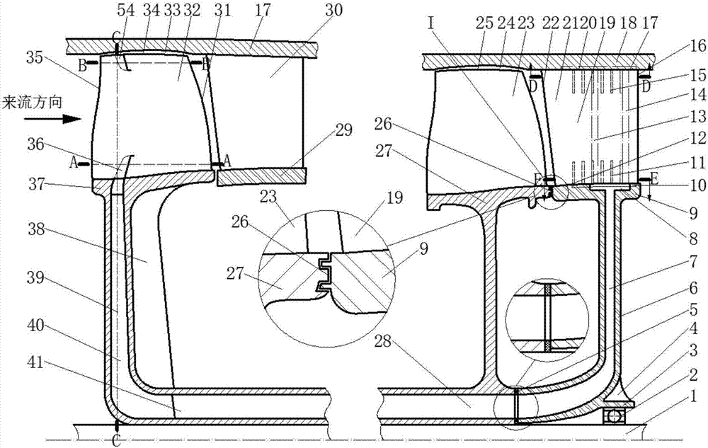
[0029] like figure 1 As shown, the multi-stage axial flow compressor of the present invention includes a target rotor blade 32, a downstream stator blade 19, a downstream stator blade disk 6, a target rotor blade disk 37 and a rotor disk drainage cavity that rotates synchronously with the engine shaft 1 28 structure; there is a tip gap 33 between the target rotor blade 32 and the casing 18, and is connected to the engine shaft 1 through the target rotor blade disc 37 with the jet gas guide cavity 40; there is no gap between the downstream stator blade 19 and the casing 18. Seam connection, with casing end wall 20 structure; seamless connection between downstream stator blade 19 and downstream stator blade hub 9, with hub end wall 12 structure; downstream stator blade disc 6 is stationary relative to casing 18, passing through the downstream stator wheel The disc bearing 2 is connected to the engine shaft 1, and is connected to the target rotor blade wheel disc 37 through the s...

Embodiment 2

[0034] like Image 6 As shown, this embodiment is basically the same as Embodiment 1, the difference is that the downstream stator with the suction slot is located immediately downstream of the target rotor blade, and there is no blade row structure between the two.


PUM


Abstract

The invention relates to a multistage axial flow gas compressor and discloses a rotating blade and stationary blade combined adjustment multistage axial flow gas compressor which comprises a target rotor blade, a downstream stator blade, a downstream stator blade wheel disk, a target rotor blade wheel disk and a rotor wheel disk drainage cavity structure rotating synchronously with an engine shaft. Through a guiding blade in a jet flow gas flow guiding cavity, drainage gas has the same convected velocity as a rotor, and a jet flow groove further acts on an end area and a blade tip of the target rotor blade. According to the characteristics of pressurizing by stages of the multistage gas compressor, a self-adaptive suction and wall-attached jet flow is formed in a downstream stator combination suction groove and the target rotor end area and the blade tip, rotor and stator three-dimensional angular area separation flowing of the multistage gas compressor is effectively inhibited, leakage flowing of the rotor blade tip is improved, rotating stall caused by three-dimensional angular area separation, blade tip front edge overflow and tail edge countercurrent flow is effectively prevented, the rotating stability of the target rotor is strengthened, the margin is increased, and the stable working condition range of the gas compressor is widened.

Description

technical field [0001] The invention relates to the field of multistage axial flow compressors, in particular to a multistage axial flow compressor with combined adjustment of rotating and stationary vanes. Background technique [0002] The compressor is the core component of the aviation gas turbine engine. It is composed of multi-stage rotors and stators that are arranged in a staggered sequence. The gradient effect is strong, and it has a complex vortex system structure; the corner separation structure at the stator end zone and the leakage flow structure at the rotor tip are the main secondary flow structures inside the compressor, and are the main sources of flow loss and blockage inside the compressor. It has a crucial impact on the performance of the compressor, such as pressure ratio, efficiency, and margin. In severe cases, it will cause the compressor to stall and surge, with catastrophic consequences. After decades of research, many scientific research works Rese...

Claims


Application Information

Patent Timeline
Patent Type & Authority Applications(China)
IPC IPC(8): F04D29/38F04D29/54F04D29/08F04D27/00F04D19/02
CPCF04D19/02F04D27/002F04D29/083F04D29/324F04D29/542F04D29/544F05D2220/32F05D2240/124F05D2240/306F05D2240/307F04D29/682F04D29/684
Inventor 陆利蓬唐雨萌柳阳威王鸣
Owner BEIHANG UNIV
Why Eureka
Try Eureka