Stator and DC brushless motors including the stator

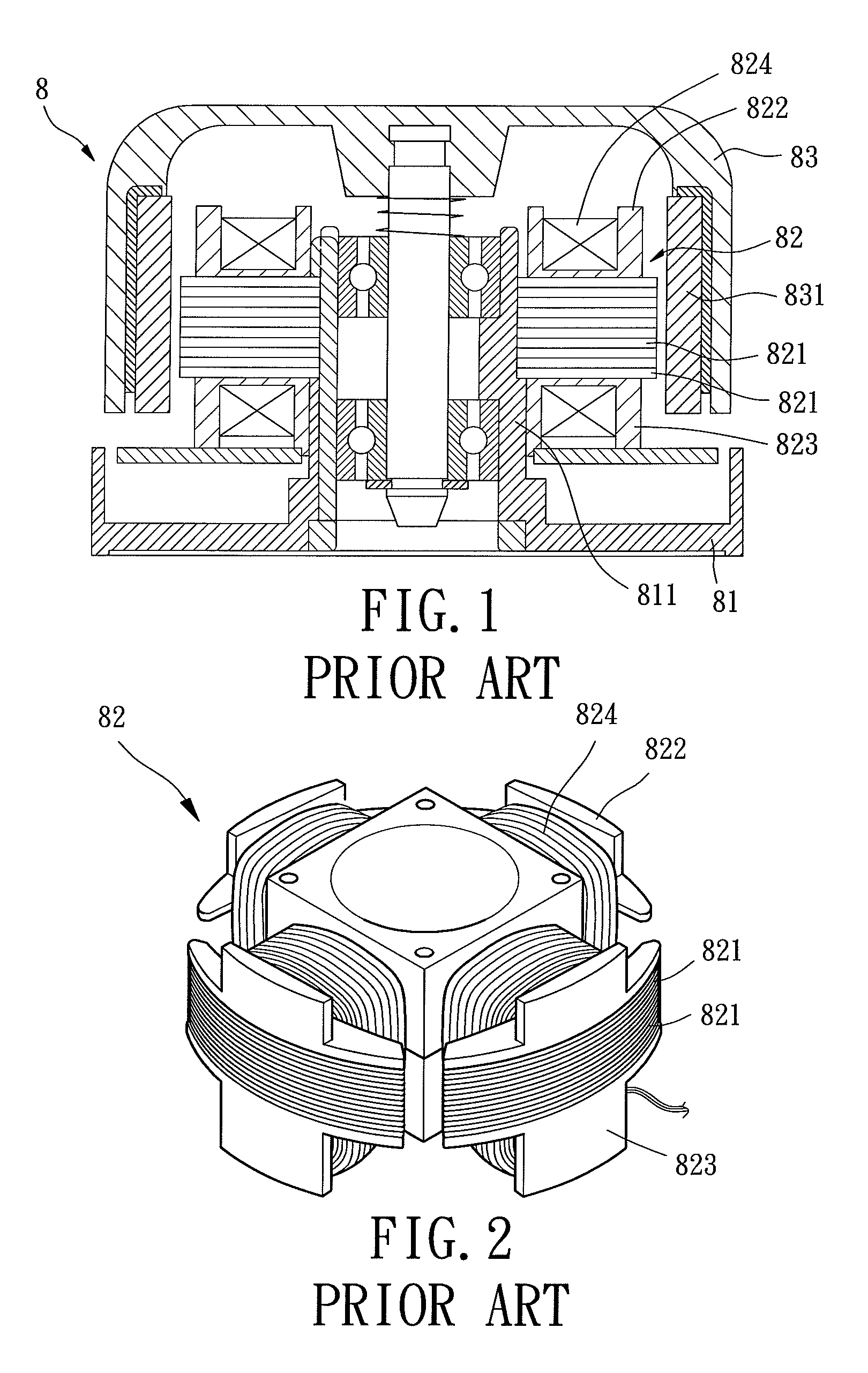
a brushless motor and stator technology, applied in the direction of dynamo-electric machines, magnetic circuits characterised by insulating materials, electrical apparatus, etc., can solve the problems of ineffective reduction of the overall axial height and overall volume of the outer rotor type motor b>8/b>, and the inability to miniaturize the outer rotor type motor b>8/b>, and achieves low rotational stability, high manufacturing cost, and low

Active Publication Date: 2011-10-04
SUNONWEALTH ELECTRIC MACHINE IND
View PDF5 Cites 9 Cited by
  • Summary
  • Abstract
  • Description
  • Claims
  • Application Information

AI Technical Summary

Benefits of technology

[0008]The primary objective of the present invention is to provide a DC brushless motor to solve the disadvantages of conventional inner and outer rotor type motors including high manufacturing costs, assembling inconvenience, difficulties in reducing the axial height, and low rotational stability.
[0017]Since the stator according to the preferred teachings of the present invention does not include conventional silicon steel plates and is comprised of an annular insulating ring and a coil unit, advantages including low manufacturing costs, assembling convenience, possible reduction in the axial height, and high rotational stability are obtained.

Problems solved by technology

The stator 82 has many components and, thus, a complicated structure, resulting in high manufacturing costs and assembling inconvenience.
Furthermore, the axial height of the stator 82 is relatively large, such that the overall volume and the overall axial height of the outer rotor type motor 8 can not be effectively reduced.
As a result, miniaturization of the outer rotor type motor 8 is almost impossible.
The stator 92 of the inner rotor type motor 9 is substantially the same as the stator 82 of the outer rotor type motor 8 and, thus, has the same disadvantages including high manufacturing costs, assembling inconvenience, difficulties in reducing the axial height, and low rotational stability.

Method used


Image

  • Stator and DC brushless motors including the stator
  • Stator and DC brushless motors including the stator
  • Stator and DC brushless motors including the stator

Examples


first embodiment

[0044]FIGS. 5 and 6 show a DC brushless motor 1 of a first embodiment according to the preferred teachings of the present invention. The DC brushless motor 1 is of outer rotor type and includes a base 11, a circuit board 12, a stator 13, and a rotor 14. The base 11 includes a pivotal portion 111 in the form of a shaft tube receiving elements such as a fixing ring 112, a retaining plate 113, a bearing 114, and an abrasion-resistant plate 115, so that the rotor 14 can rotate smoothly in the pivotal portion 111. Although the pivotal portion 111 shown in FIGS. 5 and 6 is a shaft tube, the pivotal portion 111 can be in any other form including, but not limited to, a shaft base or other structure for rotatably coupling with the rotor 14. The circuit board 12 is mounted to the base 11 for activating the stator 13 to drive the rotor 14 to rotate.

[0045]With reference to FIG. 7, the stator 13 includes an annular insulating ring 131 and a coil unit 132. Preferably, the annular insulating ring ...

second embodiment

[0051]FIG. 10 shows a DC brushless motor 2 of a second embodiment according to the preferred teachings of the present invention. The DC brushless motor 2 is of inner rotor type and includes a housing 21, a circuit board 22, a stator 23, and a rotor 24. The housing 21 includes two pivotal portions 211 each receiving a bearing and a retaining ring for stably supporting the rotor 24. Although the housing 21 shown in FIG. 10 includes two pivotal portions 211, the housing 21 can include only one pivotal portion 211 or more than two pivotal portions 211. The circuit board 22 is mounted to the housing 21 for activating the stator 23 to drive the rotor 24 to rotate.

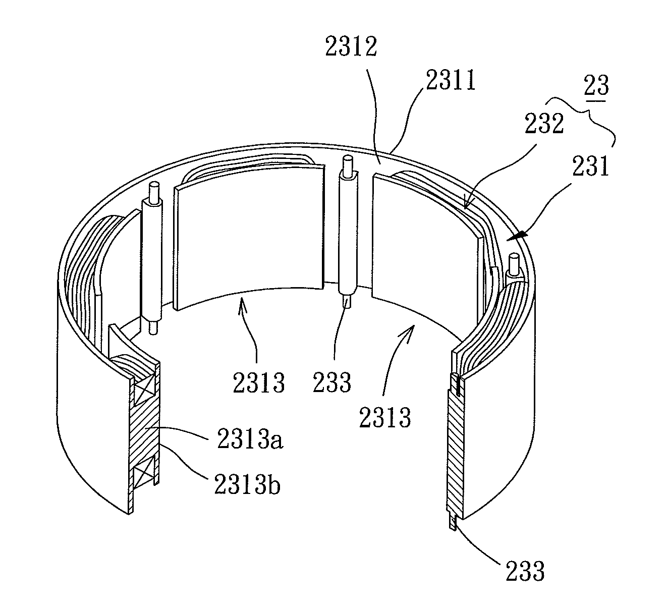
[0052]With reference to FIG. 11, the stator 23 is mounted in the housing 21 and includes an annular insulating ring 231 and a coil unit 232. Preferably, the annular insulating ring 231 is a ring integrally formed from an insulating material. The annular insulating ring 231 includes an outer peripheral face 2311 and an inner perip...

third embodiment

[0062]With reference to FIG. 16, the stator 43 is mounted in the housing 41 and includes an annular insulating ring 431 and a coil unit 432. Preferably, the annular insulating ring 431 is a ring integrally formed from an insulating material. The annular insulating ring 431 includes an outer peripheral face 4311 and an inner peripheral face 4312. The outer peripheral face 4311 faces the inner periphery of the housing 41. A plurality of winding portions 4313 extends from each of the outer and inner peripheral faces 4311 and 4312. Each winding portion 4313 of the stator 43 includes a rib 4313a and a stop plate 4313b. The coil unit 432 is wound around the winding portions 4313 and electrically connected to the circuit board 42. The stator 43 is substantially the same as the stator 33 of the third embodiment and, therefore, not described in detail to avoid redundancy.

[0063]In the DC brushless motor 4 according to the preferred teachings of the present invention, the stator 43 does not in...


PUM


Abstract

A stator for a DC brushless motor includes an annular insulating ring integrally formed from an insulating material. The annular insulating ring includes an outer peripheral face and an inner peripheral face. A plurality of winding portions extends from at least one of the outer and inner peripheral faces. A coil unit is wound around each of the plurality of winding portions. The stator can be utilized in various DC brushless motors. Since the stator does not include conventional silicon steel plates and is comprised of an annular insulating ring and a coil unit, advantages including low manufacturing costs, assembling convenience, possible reduction in the axial height, and high rotational stability are obtained.

Description

BACKGROUND OF THE INVENTION[0001]1. Field of the Invention[0002]The present invention relates to a stator and DC brushless motors including the stator and, more particularly, to a stator without silicon steel plates and DC brushless motors including the stator.[0003]2. Description of the Related Art[0004]Currently available DC brushless motors include an outer rotor type and an inner rotor type. Outer rotor type motors have advantages of simple structure, good heat dissipation, and low costs, whereas inner rotor type motors have better rotational stability.[0005]FIGS. 1 and 2 show a conventional outer rotor type motor 8 including a base 81, a stator 82, and a rotor 83. The base 81 includes a shaft tube 811. The stator 82 is mounted to an outer periphery of the shaft tube 811. The rotor 83 includes a permanent magnet 831 and is rotatably extended through the shaft tube 811. More specifically, the stator 82 of the motor 8 includes a plurality of silicon steel plates 821, an upper insu...

Claims


Application Information

Patent Timeline
Patent Type & Authority Patents(United States)
IPC IPC(8): H02K1/04
CPCH02K1/146H02K1/185H02K1/187
Inventor HORNG, ALEXYIN, TSO-KUO
Owner SUNONWEALTH ELECTRIC MACHINE IND
Why Eureka
Try Eureka