

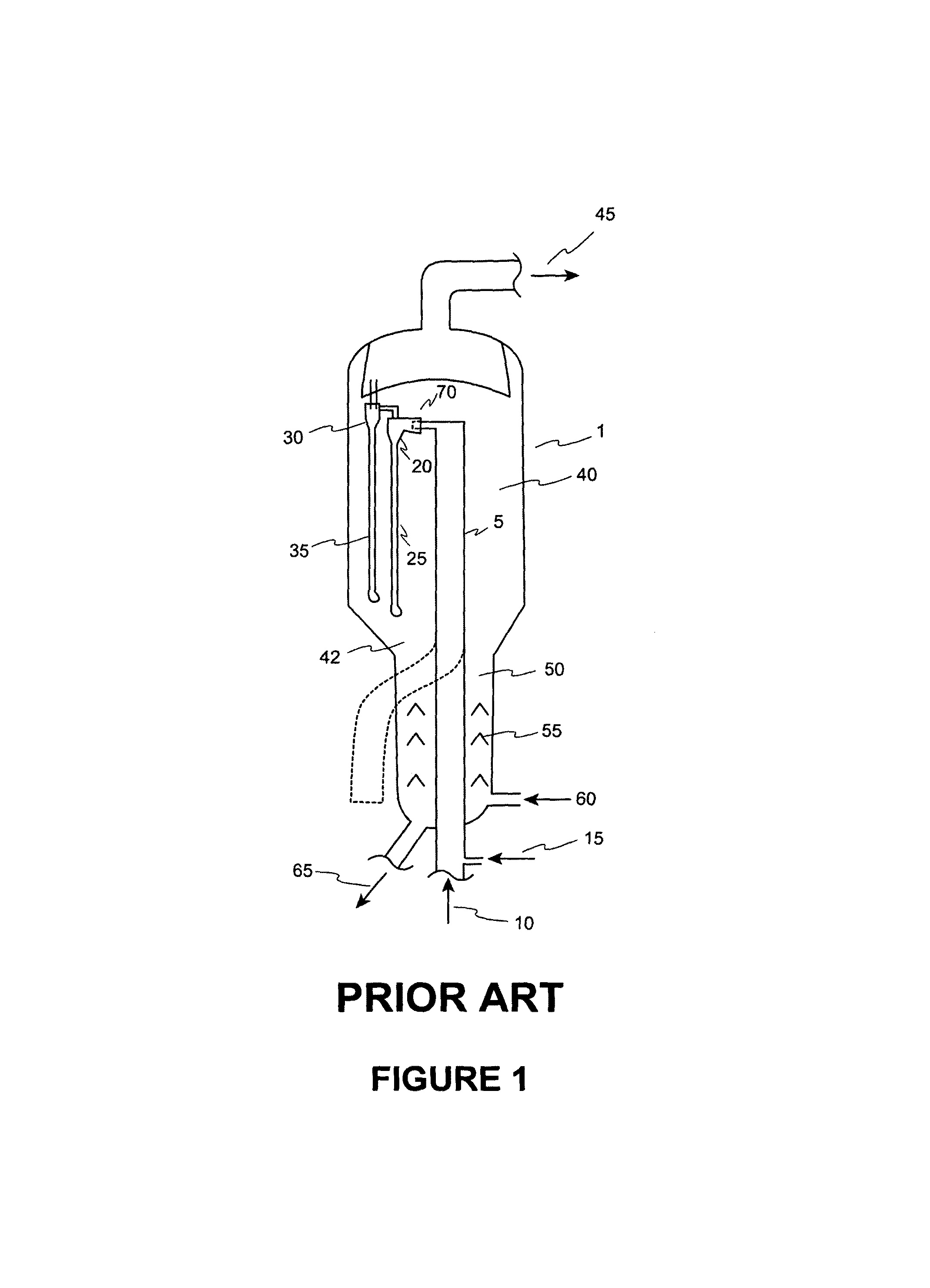
FCC reactor and riser design for short contact-time catalytic cracking of hydrocarbons
a technology of hydrocarbon cracking and reactor, which is applied in the direction of furnaces, lighting and heating apparatuses, furnace types, etc., can solve the problems of uncontrolled catalyst/hydrocarbon contact time, and hydrocarbon feed materials overcracking
- Summary
- Abstract
- Description
- Claims
- Application Information
AI Technical Summary
Benefits of technology
Problems solved by technology
Method used
Image

Examples
example
[0100]In this Example, extensive cold flow testing of the current invention and the prior art was performed. This testing consisted of running see-through plexiglass models of both the prior art, wherein the disengaging zone is in the conduit between the riser and the primary conduits, and a preferred embodiment of the present invention configurations at scaled sizes and operating conditions using air in place of hydrocarbons and steam. Gas escaping through the vents was measured with helium tracers and probes. Catalyst escaping through the vent was collected and weighed. A diagram of the setup of the cold flow test facility of the prior art design is shown in FIG. 6A, while a picture of this cold flow test facility that was utilized is shown in FIG. 6B. A diagram of the setup of the cold flow test facility of a preferred embodiment of the present invention is shown in FIG. 7A, while a picture of this cold flow test facility that was utilized is shown in FIG. 7B.
[0101]It should be n...
PUM
| Property | Measurement | Unit |
|---|---|---|
| velocity | aaaaa | aaaaa |
| velocity | aaaaa | aaaaa |
| angle | aaaaa | aaaaa |
Abstract
Description
Claims
Application Information