Interferometric device for position measurement and coordinate measuring machine

an interferometer and position measurement technology, applied in measurement devices, instruments, using optical means, etc., can solve problems such as instability of laser frequency and erroneous measurement values, and achieve the effect of improving the repeatability of measuring and improving the accuracy of position measuremen

Active Publication Date: 2013-01-08
VISTEC SEMICON SYST
View PDF15 Cites 0 Cited by
  • Summary
  • Abstract
  • Description
  • Claims
  • Application Information

AI Technical Summary

Benefits of technology

[0012]It is an object of the present invention to improve the measuring repeatability and the measuring precision of position measurements with interferometers and interferometer components.
[0018]Further, it is an object of the present invention to create a coordinate measuring machine with which the precision and repeatability with respect to position measurements of a measuring stage are enhanced.
[0027]It is advantageous if a beam splitter is arranged downstream at least of the beam splitter of the interferometric device which splits the measuring light into a first beam path and a second beam path, and of the beam splitter which directs the third beam path onto an etalon via an interferometer. This beam splitter directs the measuring light in the first and second partial beam paths onto the respective reflecting surface of the moveable element. A further embodiment provides that a beam splitter is arranged upstream of the beam splitter which splits the measuring light into the first and second partial beam paths. In this embodiment, in the first and second partial beam paths, respective reflecting elements are provided for directing the measuring light on the reflecting surface of the moveable element 20. The beam splitters can each have a beam trap associated with them for trapping the light reflected back by each of the interferometers. It is the purpose of the apparatus according to the present invention to prevent light from passing back into the laser or the interferometer. To minimize this effect, the division ratios of the beam splitters present in the interferometric device are to be configured in such a way that back reflections into the laser and / or the interferometer are minimized, wherein, however, sufficient light is still present for the interferometric determination of the position of the measuring stage.

Problems solved by technology

It is always necessary to measure the reference wavelength since ambient influences have an effect on the wavelength of the measuring light and would therefore lead to an erroneous measuring value.
This optical feedback leads to instability in the laser frequency.

Method used


Image

  • Interferometric device for position measurement and coordinate measuring machine
  • Interferometric device for position measurement and coordinate measuring machine
  • Interferometric device for position measurement and coordinate measuring machine

Examples


Embodiment Construction

[0043]For the same or equivalent elements of the invention, identical reference numerals will be used. Further, only reference numerals will be shown in the figures for clarity, which are necessary for describing each figure. The embodiments shown are only examples of how the apparatus according to the present invention can be configured and are not an exhaustive limitation.

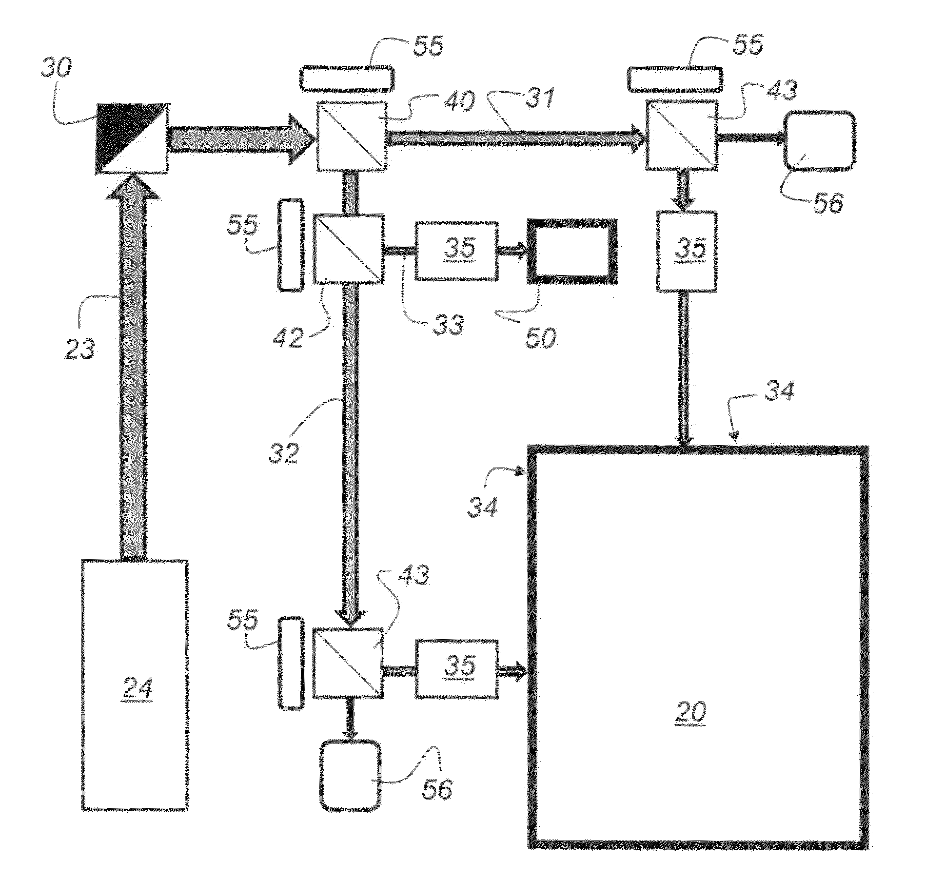
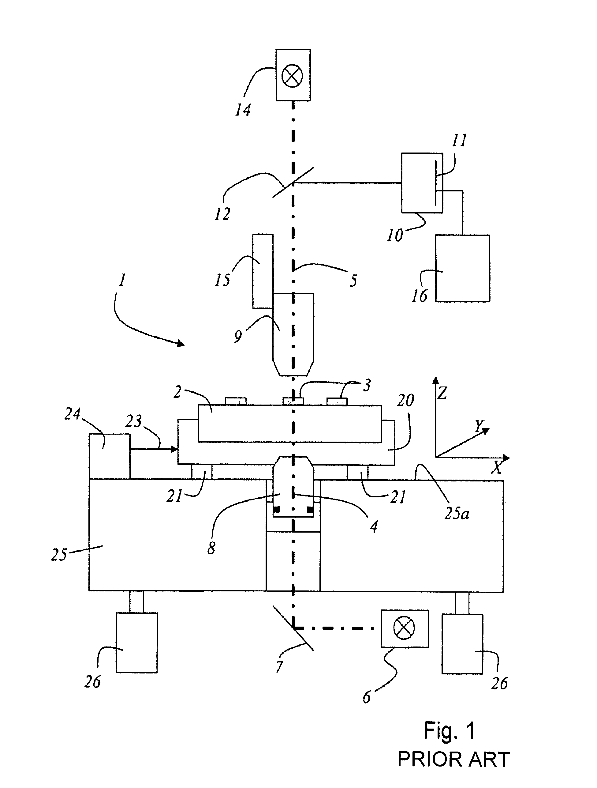
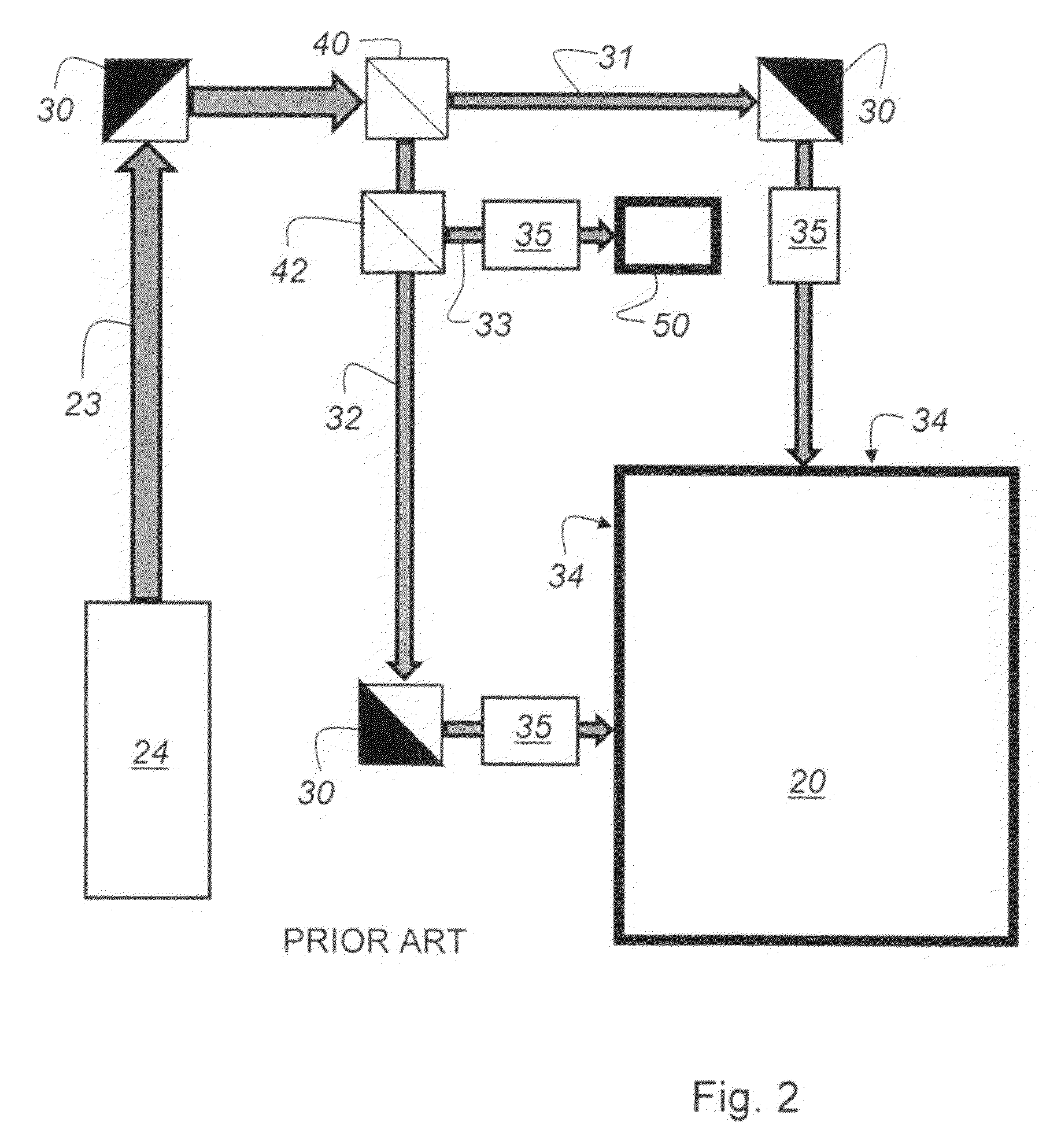
[0044]A coordinate measuring machine 1 of the type shown in FIG. 1 is repeatedly known from the prior art and also described there. For completeness sake, the functioning and arrangement of the individual elements of the coordinate measuring machine will be explained. It should also be noted that a coordinate measuring machine 1 can be used to measure positions of structures 3 on the surface 2a of a substrate 2 (mask for the manufacture of semiconductors). These measurements are carried out optically. Herein, the measuring stage 20, which is formed as a reflecting body, is traversed in a plane 25a in the X coordi...


PUM


Abstract

An interferometric device for position measurement of an element moveable in a plane is disclosed. A laser light source measures the position of the moveable element and emits the required measuring light. A beam splitter splits the measuring light into a first partial beam path and a second partial beam path, which each impinge on a reflecting surface of the moveable element via an interferometer. Herein, at least the beam splitter, which splits the measuring light into a first partial beam path and a second partial beam path, and the beam splitter, which directs the third partial beam path onto an etalon via an interferometer, have a respective beam trap associated with them, which traps the light returning from the respective interferometers.

Description

[0001]This claims the benefit of German Patent Application No. 10 2008 002 968.8, filed on Jul. 25, 2008 and hereby incorporated by reference herein.[0002]The present invention relates to an interferometric device for position measurement.[0003]The invention further relates to a coordinate measuring machine.BACKGROUND[0004]Since the requirement as to the precision, reproducibility or repeatability of the parameters (position of structures on a substrate or width of structures on a substrate) determined by a coordinate measuring machine has become more stringent, it is now necessary to improve the measuring precision of the interferometer used for position measurement. The interferometers are used to measure the position of the measuring stage which moves in a plane aligned in an X coordinate direction and a Y coordinate direction.[0005]German Patent Application DE 10 2007 030 390.6 discloses a coordinate measuring machine and a method for calibrating the coordinate measuring machine...

Claims


Application Information

Patent Timeline
Patent Type & Authority Patents(United States)
IPC IPC(8): G01B11/02
CPCG01B11/03G01B21/042G01B9/02021G01B9/02027G01B2290/70G01B2290/25G01B2290/60
Inventor BOESSER, HANS-ARTURKLUGE, SIEGFRIED PETERLENZ, JOERGNICKEL, GERHARD JOSEPH
Owner VISTEC SEMICON SYST
Why Eureka
Try Eureka