Convergence of air water cooling of an electronics rack and a computer room in a single unit

a technology of air water cooling and electronics rack, which is applied in the direction of domestic cooling apparatus, electrical apparatus casings/cabinets/drawers, instruments, etc., can solve problems such as difficult applicability, and achieve the effect of facilitating monitoring of system coolant temperatur

Inactive Publication Date: 2013-01-08
INT BUSINESS MASCH CORP
View PDF43 Cites 49 Cited by
  • Summary
  • Abstract
  • Description
  • Claims
  • Application Information

AI Technical Summary

Problems solved by technology

This trend poses a cooling challenge at both module and system level.
However, this approach is becoming problematic at the rack level in the context of a computer installation (i.e., data center).

Method used


Image

  • Convergence of air water cooling of an electronics rack and a computer room in a single unit
  • Convergence of air water cooling of an electronics rack and a computer room in a single unit
  • Convergence of air water cooling of an electronics rack and a computer room in a single unit

Examples


Embodiment Construction

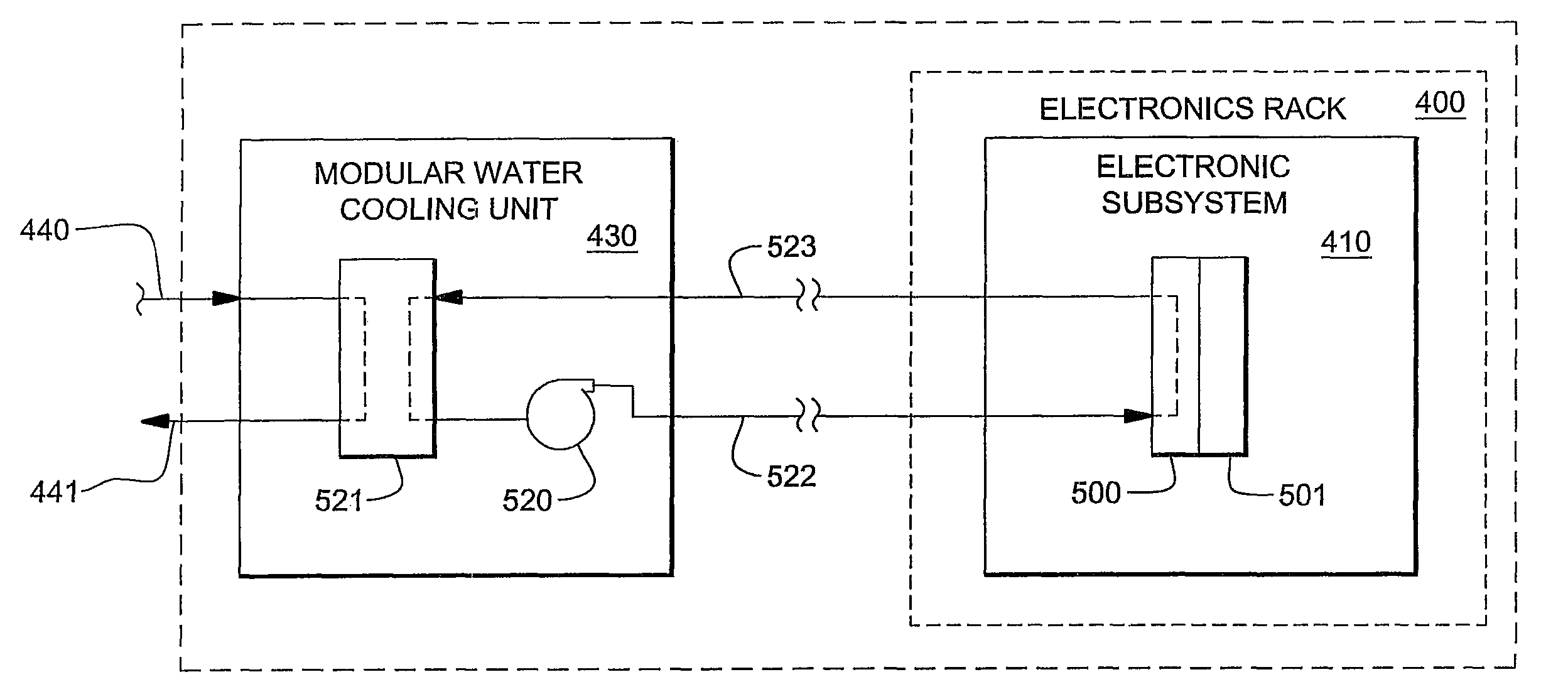
[0028]As used herein, the terms “electronics rack,”“rack-mounted electronic equipment,” and “rack unit” are used interchangeably, and unless otherwise specified include any housing, frame, rack, compartment, blade server system, etc., having one or more heat-generating components of a computer system or electronics system, and may be, for example, a stand alone computer processor having high, mid or low end processing capability. In one embodiment, an electronics rack may comprise multiple electronics subsystems, each having one or more heat-generating components disposed therein requiring cooling. “Electronics subsystem” refers to any sub-housing, blade, book, drawer, node, compartment, etc., having one or more heat-generating electronic components disposed therein. Each electronics subsystem of an electronics rack may be movable or fixed relative to the electronics rack, with the rack-mounted electronics drawers of a multidrawer rack unit and blades of a blade center system being ...


PUM


Abstract

Systems and methods are provided for cooling an electronics rack and a computer room from a single unit, which includes a heat-generating electronics subsystem across which air flows from an air inlet to an air outlet side of the rack. First and second modular cooling units (MCUs) are associated with the rack and configured to provide system coolant to the electronics subsystem for cooling thereof. System coolant supply and return manifolds are in fluid communication with the MCUs for facilitating providing of system coolant to the electronics subsystem, and to an air-to-liquid heat exchanger associated with the rack for exclusively cooling air passing through the rack, as well as conditioning the ambient air of the computer room. Such cooling is exclusive of an outside-of-rack conditioned air unit.

Description

PRIORITY CLAIM[0001]The present application is a continuation-in-part of U.S. patent application Ser. No. 11 / 942,207, filed Nov. 19, 2007, and entitled “System and Method for Facilitating Cooling of a Liquid-Cooled Electronics Rack.” Benefit of priority is hereby claimed under 35 U.S.C. §120 to U.S. patent application Ser. No. 11 / 942,207, which is incorporated by reference herein in its entirety and for all purposes.CROSS REFERENCE TO RELATED APPLICATIONS[0002]The present application is related to the following United States patent application, which is hereby incorporated by reference in its entirety:[0003]1) U.S. patent application Ser. No. 12 / 425,210[0004]This invention was made with United States Government support under Agreement No. HR0011-07-9-0002 awarded by DARPA. The Government has certain rights in this invention.TECHNICAL FIELD[0005]The present invention relates in general to apparatuses and methods for facilitating operation of liquid-cooled, rack-mounted assemblages of...

Claims


Application Information

Patent Timeline
Patent Type & Authority Patents(United States)
IPC IPC(8): G06F1/20
CPCH05K7/20745H05K7/20809
Inventor ARIMILLI, RAVI K.ELLSWORTH, JR., MICHAEL J.SEMINARO, EDWARD J.
Owner INT BUSINESS MASCH CORP
Why Eureka
Try Eureka