
Mobile oil field rig with air bearing transport

a technology of air bearings and mobile rigs, which is applied in the direction of transportation and packaging, mechanical conveyors, vehicle components, etc., can solve the problems of high labor intensity, time-consuming, and often dangerous types of operations, and achieve the effect of reducing the pressure of ground bearings and reducing moving friction

Inactive Publication Date: 2013-01-22
VOORHEES RONALD J
View PDF3 Cites 17 Cited by
  • Summary
  • Abstract
  • Description
  • Claims
  • Application Information

AI Technical Summary

Benefits of technology

The rig transport system uses air bearings to lift and move drilling and workover rigs without having to disassemble them. This reduces pressure on the ground and the friction of moving, resulting in a more efficient and safe transportation process.

Problems solved by technology

Whichever type of support is used, this type of operation is labor intensive, time consuming, and often dangerous.
All the time that is spent in such a move is lost production time.

Method used


Image

  • Mobile oil field rig with air bearing transport
  • Mobile oil field rig with air bearing transport
  • Mobile oil field rig with air bearing transport

Examples


Embodiment Construction

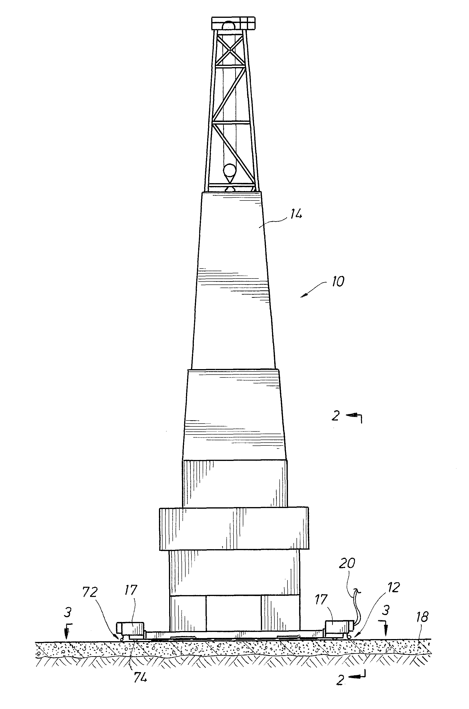
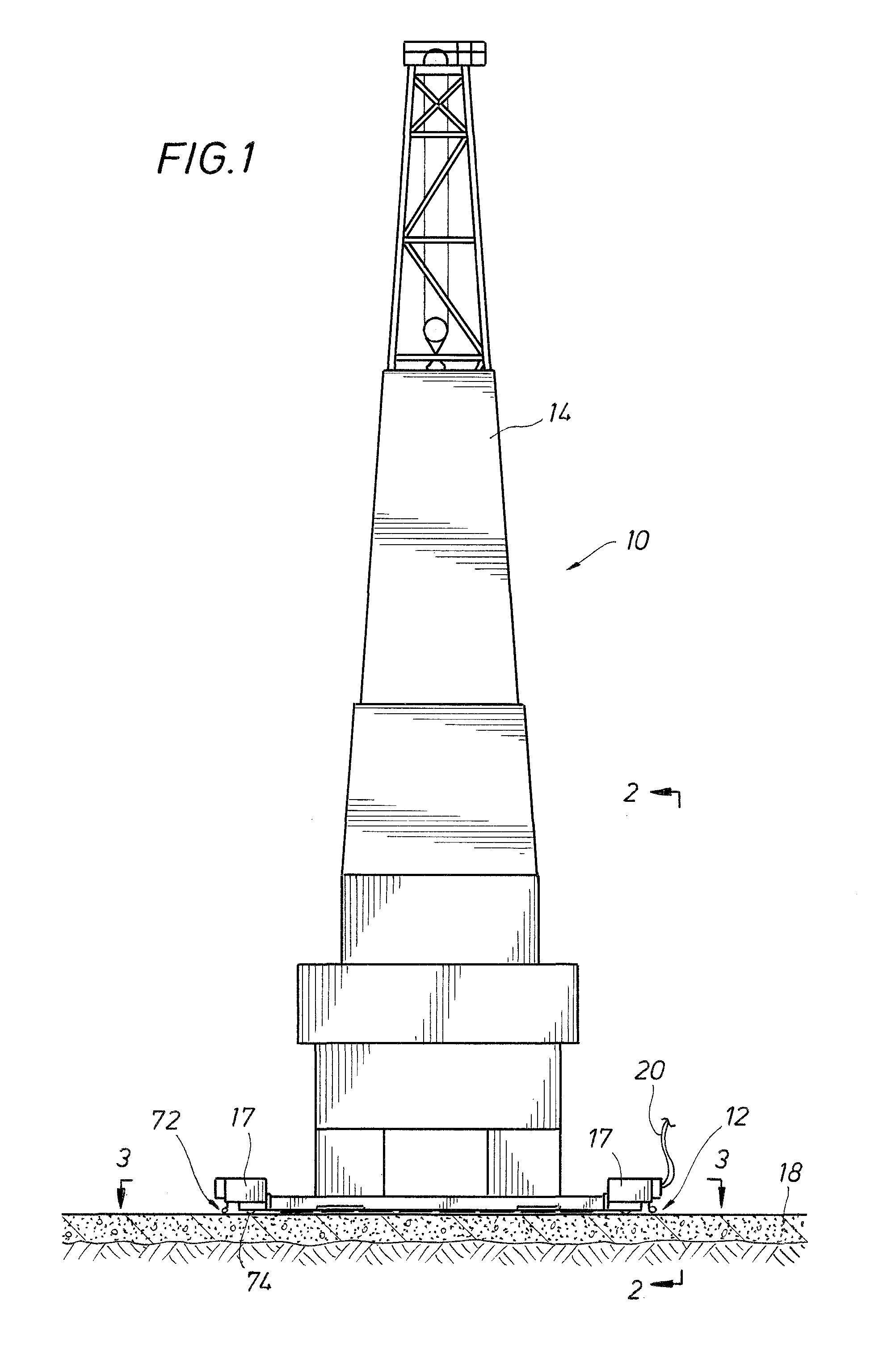
[0020]FIG. 1 depicts a field rig 10 supported for transport on an air bearing subsystem 12. As used herein, the term “rig” refers to either a drilling rig or a workover rig, since the air bearing transport shown and described herein is equally adaptable to either type of rig. During transport of the rig 10, a derrick structure 14 remains erect and intact so that the rig is ready for work as soon as it reaches a new site. In other systems known in the art, the entire derrick structure must be dismantled or lowered to a horizontal position in order to move the rig from one well to another.

[0021]Preferably, the system includes a set of self-propelled wheels 16 driven by a drive system 17, although other means of moving the rig may be used, in conjunction with the air bearing subsystem 12. The drive subsystem will be described below in greater detail in respect of FIGS. 7 and 8.

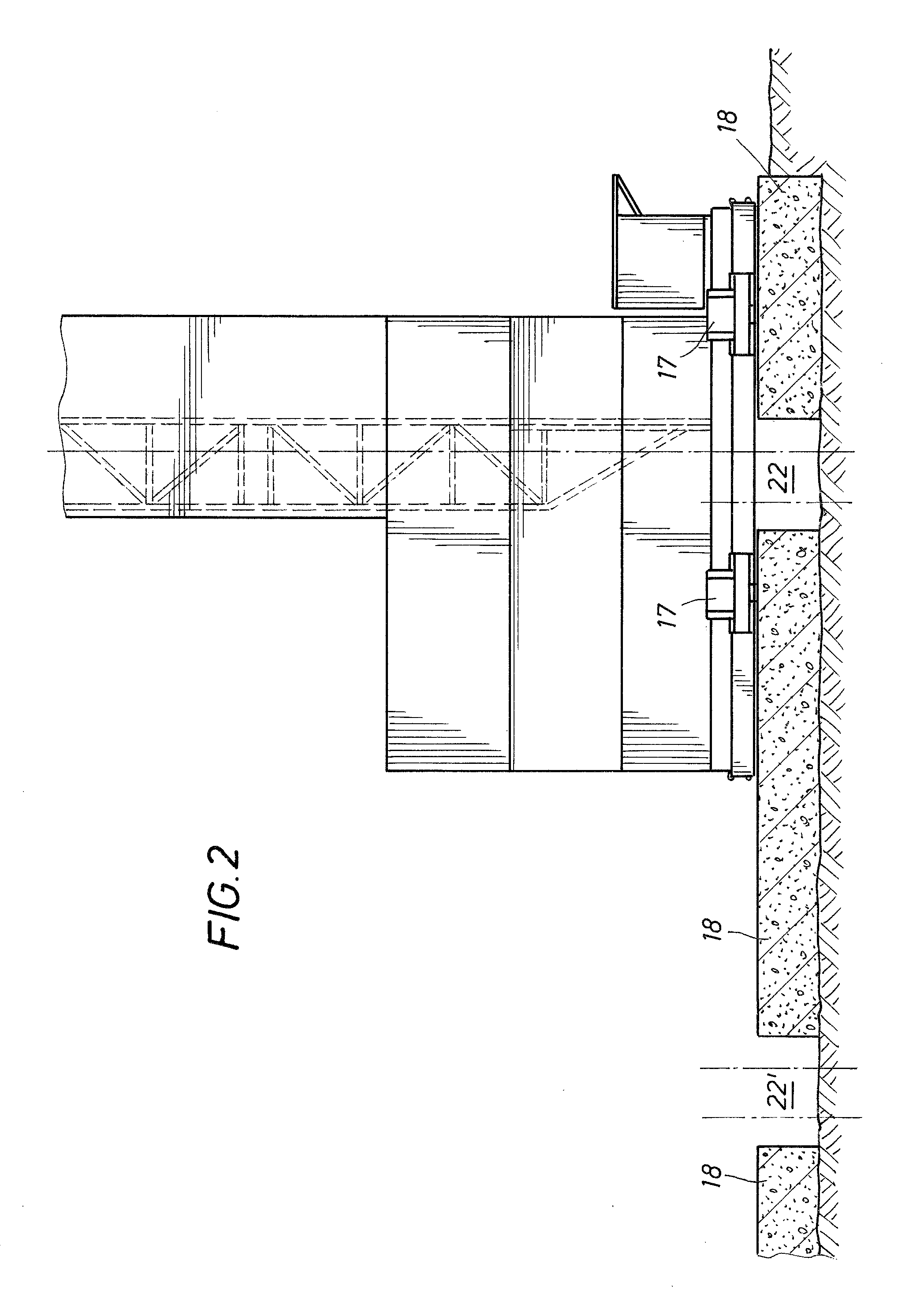
[0022]As shown in FIG. 1, the rig moves along a concrete track or pad 18, moving various auxiliary equipment a...


PUM


Abstract

A rig transport system provides an air bearing subsystem supporting a drilling and workover rig. The transport system moves the entire rig without having to disassemble the rig, including leaving the derrick in a vertical standing position, along one of a pair of parallel tracks. The air bearing subsystem distributes the rig load over a large footprint to reduce ground bearing pressure. The air bearings lift the load so that the entire rig rides on a film of air, thereby reducing moving friction by up to about 96%.

Description

FIELD OF THE INVENTION[0001]The present invention relates generally to the field of oil field drilling and workover rigs, and, more particularly, to a mobile rig that rides on air bearings for movement from one work location to another.BACKGROUND OF THE INVENTION[0002]Oil and gas rigs are used in the field for many purposes, including drilling, workover, and maintenance operations. Land-based drilling rigs generally consist of engines, a drawworks, a mast (or derrick), pumps to circulate the drilling fluid (mud) under various pressures, blowout preventers, drill string and related equipment. The engines power the different pieces of equipment, including a rotary table or top drive that turns the drill string, causing the drill bit to bore through the subsurface rock layers. Rock cuttings are carried to the surface by the circulating drilling fluid. The intended well depth, bore hole diameter and drilling site conditions are the principal factors that determine the size and type of r...

Claims


Application Information

Patent Timeline
Patent Type & Authority Patents(United States)
IPC IPC(8): B65G35/00
CPCB65G7/06
Inventor VOORHEES, RONALD J.
Owner VOORHEES RONALD J
Learn More