
Scale coupling system

a coupling system and scale technology, applied in the field of geometric instruments, can solve the problems of difficult to achieve perfect alignment, spacing and angles, and large evidence area for the range of scale sizes available to users, and achieve the effect of avoiding the occurrence of overlapping, overlapping, and overlapping

Inactive Publication Date: 2013-01-29
SCHNEIDER JAMES C
View PDF40 Cites 6 Cited by
  • Summary
  • Abstract
  • Description
  • Claims
  • Application Information

AI Technical Summary

Benefits of technology

The patent describes a coupler and a method to connect forensic scales together. The coupler has a track with tabs and edge walls that make it easy to slide the arms of the scales in a fixed angle. The coupler also has a registration stop to ensure accurate measurements. To use the coupler, two scales are connected together and the ruler arms are slidably engaged in the track to maintain accuracy. The coupler simplifies the process of creating a customizable scale by allowing any desired ruler arm configuration to be assembled.

Problems solved by technology

Unfortunately, the evidence area is often too large for the range of scale sizes that the user has available.
Obviously, it is difficult to achieve perfect alignment, spacing, and angles, especially if laid out on the irregular contours of a person's body.
The work-around in use now is to utilize a computer to manipulate the photographic image as needed to create an accurate grid of measurement intervals, but then that may cause questions about validity of the evidence.
It can be seen that Kaminski's evidence marker does not provide a common scale marking zero point to align two or more scales to accurately measure evidence, therefore this requires forensic personnel to calculate the distance between two scales connected according to Kaminski's disclosure.
Furthermore, the separation distance and relative angle between Kaminski's connected scales can change because the leg unit frictionally holds the scales on only one edge, which allows the scales to be inadvertently moved out of relative position while in use.
There is also a vertical leg that interferes with use in a planar configuration.

Method used


Image

  • Scale coupling system
  • Scale coupling system
  • Scale coupling system

Examples


Embodiment Construction

[0053]Some Definitions:

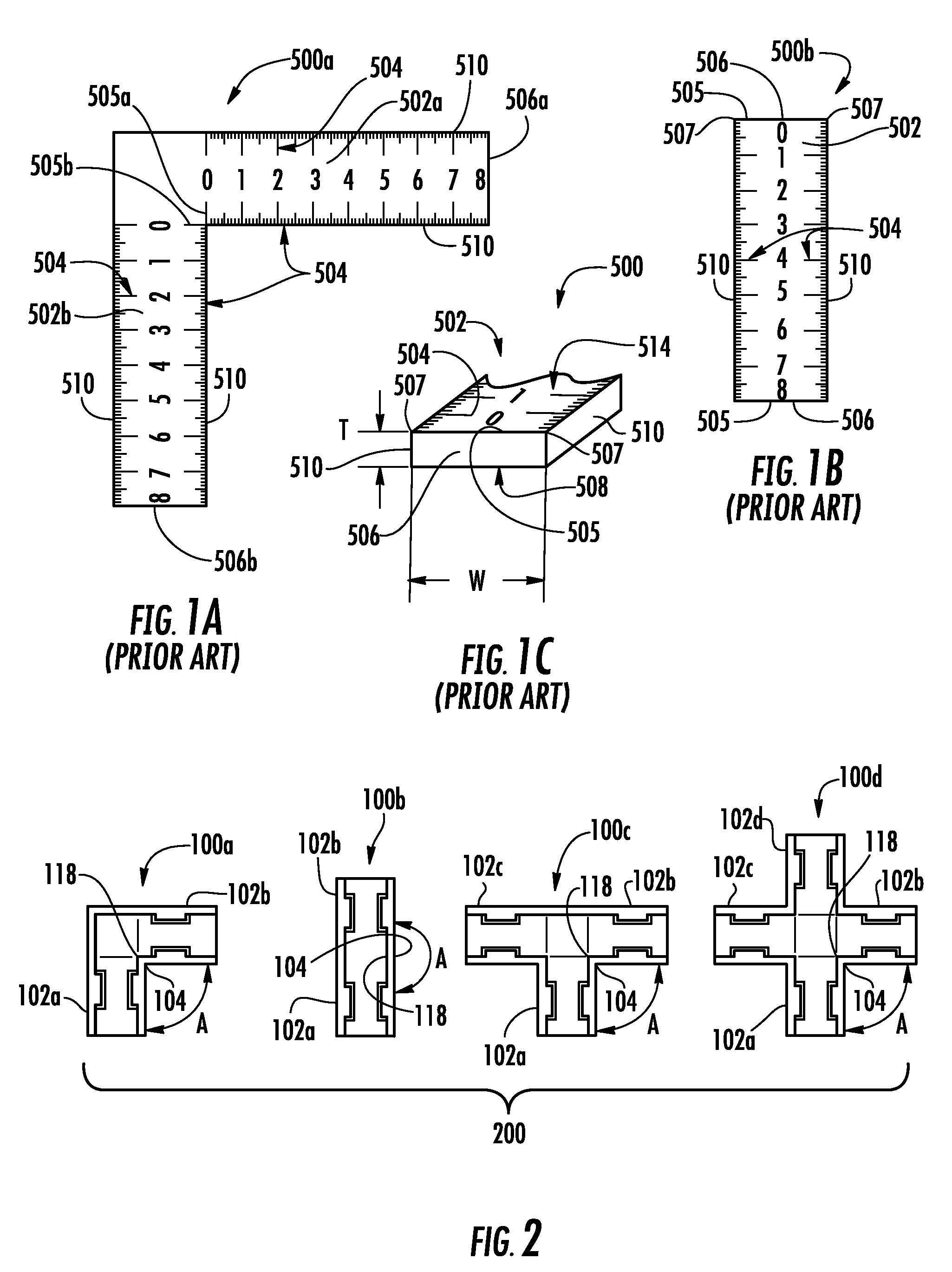
[0054]As is evident from reading prior art disclosures, terminology relevant to rulers and scales and measurement devices is presented in a variety of contexts that may blur any formal distinctions between terms such as “ruler” and “scale”, for example. This ambiguity is likely due to the fact that most “rulers” in common everyday use have both a straight edge (straightedge) suitable for making ruled (i.e., straight) lines, plus scale markings suitable for using the ruler as a scale to make measurements. Therefore, for clarity of the present disclosure, the following terms are generally defined as follows, however common sense should prevail in case a term is used in a context that obviously indicates an inadvertent alternative use of a term. The basic definitions are derived from a current dictionary.[0055]scale: a sequence of scale markings at measurement intervals, used as a reference in making measurements; also a measuring instrument with such scale marki...


PUM


Abstract

A collection of couplers and a corresponding coupling method that removably connect existing forensic scales to create a coupled scale, wherein a ruler arm of each scale is slidingly engaged in a track of the coupler that provides and maintains arm-to-arm angular accuracy for scales coupled in a fixed angle, co-planar joint, and measurement accuracy of scale markings across the joint. The track includes a lower surface; two laterally opposed parallel edge walls extending up from the lower surface and spaced apart by a dimension suitable for slidingly engaging a ruler arm width; holding tabs that extend laterally inward from both edge walls spaced above the lower surface by a dimension suitable for slidingly engaging a ruler arm thickness; an open end; and preferably a longitudinally distal registration stop. Two coupler tracks are joined with co-planar lower surfaces; and an edge wall of each joined at a fixed angle vertex.

Description

TECHNICAL FIELD OF THE INVENTION[0001]The present invention relates to geometrical instruments having plural straightedges with linear distance scale markings thereupon and, more particularly to means for coupling said plural straightedges.BACKGROUND OF THE INVENTION[0002]In conducting an investigation of a crime, forensic personnel use various visual markers to measure and document identifying characteristics of physical evidence. Such markers are typically positioned next to an item of evidence and then photographed to provide a documentary record of the evidence (memorializing). These photographed markers can then be used in trial to show visual indicia on them that permit characterization of the item of evidence, such as height and width.[0003]Photographic documentation of crime and accident scenes, medical conditions and the like typically include one or more straightedged forensic scale(s) within the photographic view in order to establish scale and orientation so that accurat...

Claims


Application Information

Patent Timeline
Patent Type & Authority Patents(United States)
IPC IPC(8): B43L7/027
CPCB43L7/00B43L7/02G01B3/002G01B3/04B43L7/027Y10T403/32393
Inventor SCHNEIDER, JAMES C.
Owner SCHNEIDER JAMES C
Learn More