Wiper blade rubber and method for the production thereof

a technology production method, which is applied in the field of wiper blade rubber, can solve the problems of insufficient improvement of non-ideal wipe quality in particular on hydrophobic surfaces, and disadvantageous running performance, so as to improve the running performance improve the wipe quality, and improve the wipe quality of the wiper blade rubber

a technology production method, which is applied in the field of wiper blade rubber, can solve the problems of insufficient improvement of non-ideal wipe quality in particular on hydrophobic surfaces, and disadvantageous running performance, so as to improve the running performance improve the wipe quality, and improve the wipe quality of the wiper blade rubber

US8361595B2Active Publication Date: 2013-01-29ROBERT BOSCH GMBH

Image

  • Wiper blade rubber and method for the production thereof
  • Wiper blade rubber and method for the production thereof
  • Wiper blade rubber and method for the production thereof

Examples


Embodiment Construction

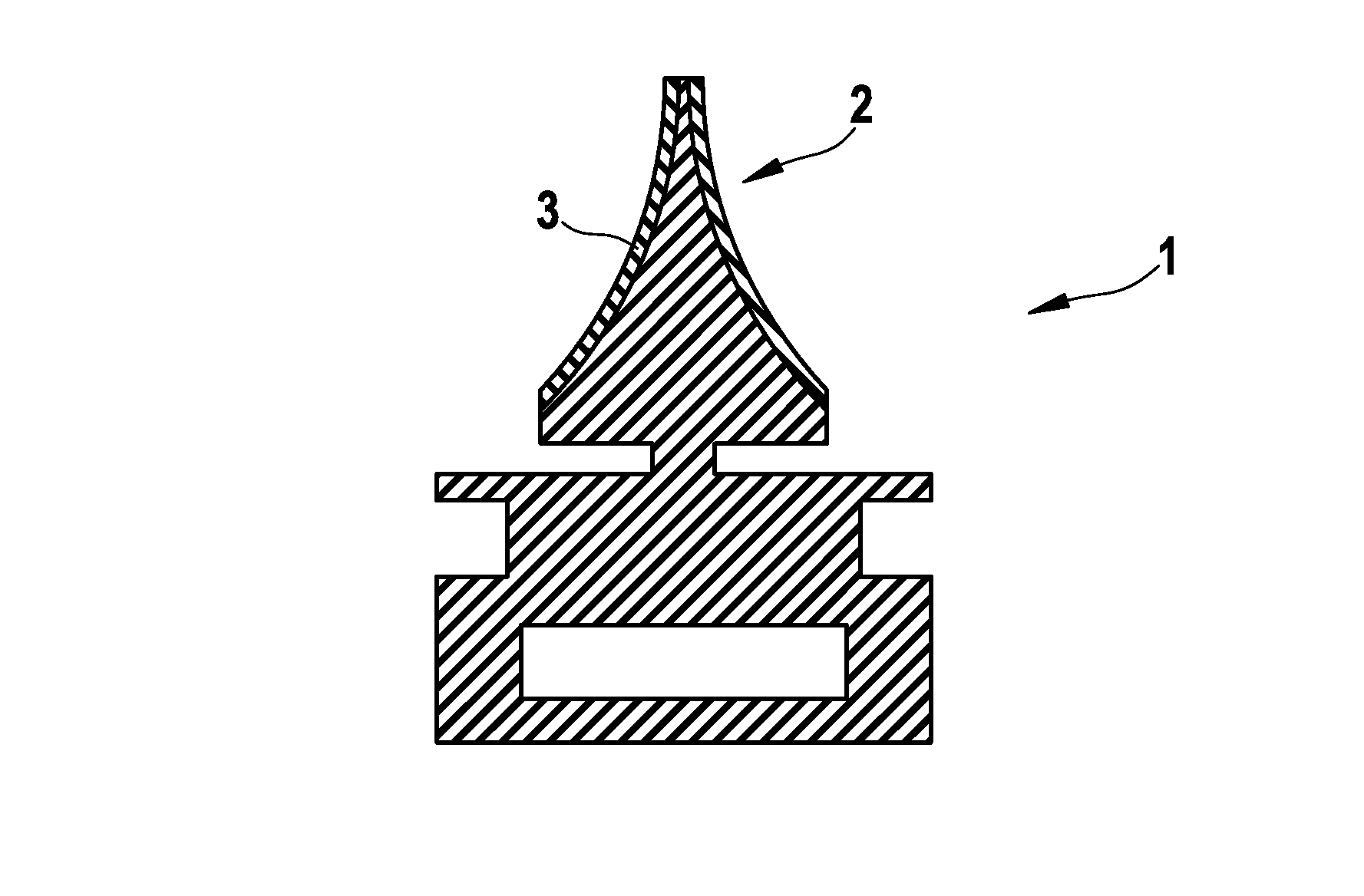
[0024]FIG. 1 shows an individual profile 1 of a wiper blade rubber 2 with a surface layer 3 applied in one embodiment of the invention after the vulcanizing process and any cleaning step, on both sides of the wiper blade rubber 2.

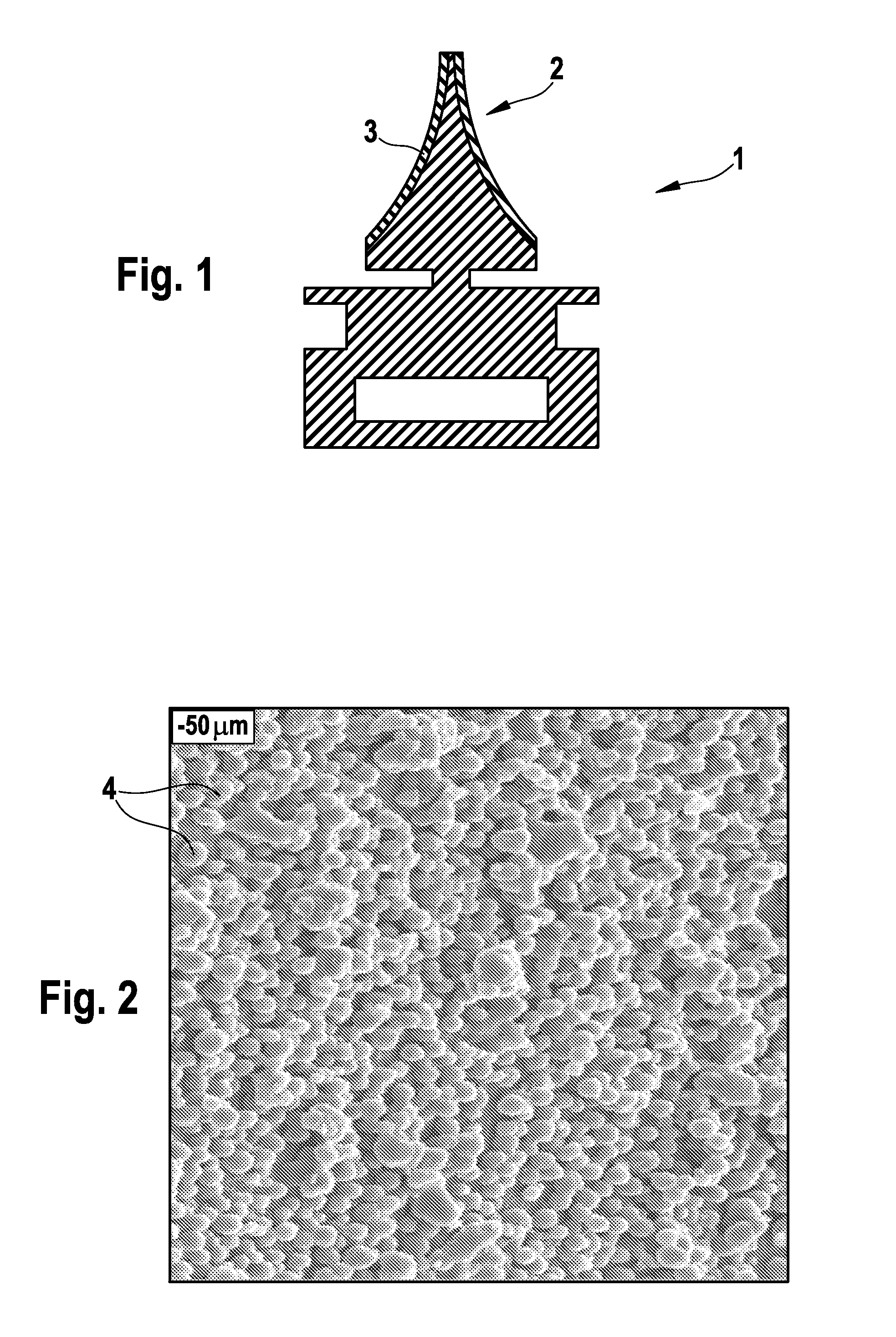
[0025]The hydrophobic and structured surface layer 3 of the wiper blade rubber 2 of the invention is illustrated by the scanning electron micrograph (SEM) in FIG. 2. The particles are indicated by 4, these being applied to the surface of the wiper blade rubber 2 and bonded thereto.

[0026]The process which can be used advantageously to achieve the surface layer 3 with hydrophobic property and surface structure encompasses the application of particles 4 or of a foil produced from a suitable material in a separate process, not described in any further detail. The particles 4 applied or the foil applied is bonded to the surface of the wiper blade rubber 2, thus producing a surface layer 3 with the desired hydrophobic property and the structuring in the micromete...


PUM

PropertyMeasurementUnit
contact angleaaaaaaaaaa
heightaaaaaaaaaa
heightaaaaaaaaaa

Abstract

The invention relates to a wiper blade rubber and a method for the production thereof, in particular for a rail wiper of a motor vehicle, made from a formed, vulcanizable elastomer material the surface of which comprises a surface layer which is hydrophobic, with a contact angle with respect to water greater than 90°, preferably greater than 120°, and a surface structure with raised regions and / or recesses in the micrometer range.

Description

BACKGROUND OF THE INVENTION[0001]The invention relates to a wiper blade rubber for a windshield wiper, in particular to a windshield wiper of a motor vehicle. It further relates to a process for production of the same.[0002]The wiper blade rubbers or wiper strips within a wiper blade of a windshield wiper serve by way of example for the removal of water droplets on a windshield of a motor vehicle and are moved back and forth by the windshield wipers of a windshield-wiper system. Wiper blade rubbers are usually molded from a hydrophobic extruded or injection-molded starting material, for example from an unvulcanized, synthetic rubber, and then vulcanized. The general requirements placed upon a wiper blade rubber encompass not only high wipe quality but also resistance to abrasion, low frictional resistance, and good slip properties on hydrophilic and hydrophobic surfaces, in order to achieve appropriate running performance of the wiper blade rubber on the various surfaces.[0003]Good ...

Claims


Application Information

Patent Timeline
29 Jan 2013
Publication
US8361595B2
IPC
B32B25/02
CPC
B60S1/38; B60S2001/3829; Y10T428/24802; Y10T428/24612; Y10T428/24355
Inventors
VAN DE ROSTYNE, KRIS; LAY, REINER