Magnetic resonance whole body antenna system, elliptically polarized with major ellipse axis tilted/non-horizontal at least when unoccupied by an examination subject

a whole body antenna and magnetic resonance technology, applied in the field of magnetic resonance systems, can solve the problems of increasing the number of components, increasing the cost of the system, and reducing the field of distribution, so as to achieve the effect of improving the field distribution

Active Publication Date: 2013-01-29
SIEMENS HEALTHCARE GMBH
View PDF10 Cites 136 Cited by
  • Summary
  • Abstract
  • Description
  • Claims
  • Application Information

AI Technical Summary

Benefits of technology

[0011]An object of the present invention is to provide a magnetic resonance system, an antenna system, a method for designing a magnetic resonance system and a method to generate magnetic resonance exposures with which an improved field distribution can be achieved with as little effort as possible in a whole-body antenna of the magnetic resonance system.
[0019]In order to achieve an elliptically distorted radio-frequency field in the whole-body antenna, in principle it is sufficient to modify the connection points so that they do not lie below an angle of 90° relative to one another along the circumference of the antenna. If two partial signals that are phase-shifted by 90° relative to one another are then fed in at these connection points, a non-circularly polarized field already inevitably forms. On the other hand, an infeed of the partial signals at an angle≠90° leads in a typical antenna to an increased reflection at the antenna inputs. This increases the power loss. The antenna structure is therefore advantageously internally fashioned so that the desired elliptically polarized field arises.
[0026]In a very simple variant, the antenna is fashioned so that at least two antenna rods located at different circumferential positions exhibit different conductor cross-sections. The antenna rods are typically fashioned in the form of printed conductor traces that are directly applied on a conduit wall of the examination tunnel. In order to construct a whole-body antenna with the desired elliptically polarized transmission characteristic, it is merely to be ensured that the conductor traces are of different widths, advantageously according to a specific pattern. Since, among other things, the conductor cross-section is representative of the inductance and thus the impedance of the respective antenna rods, a very simple variation of the impedances of the individual antenna rods is possible.

Problems solved by technology

A disadvantage of this system is that additional components 30, 31 are required in order to affect the field in the desired manner.
Such designs are naturally also relatively complicated and expensive.

Method used


Image

  • Magnetic resonance whole body antenna system, elliptically polarized with major ellipse axis tilted/non-horizontal at least when unoccupied by an examination subject
  • Magnetic resonance whole body antenna system, elliptically polarized with major ellipse axis tilted/non-horizontal at least when unoccupied by an examination subject
  • Magnetic resonance whole body antenna system, elliptically polarized with major ellipse axis tilted/non-horizontal at least when unoccupied by an examination subject

Examples


Embodiment Construction

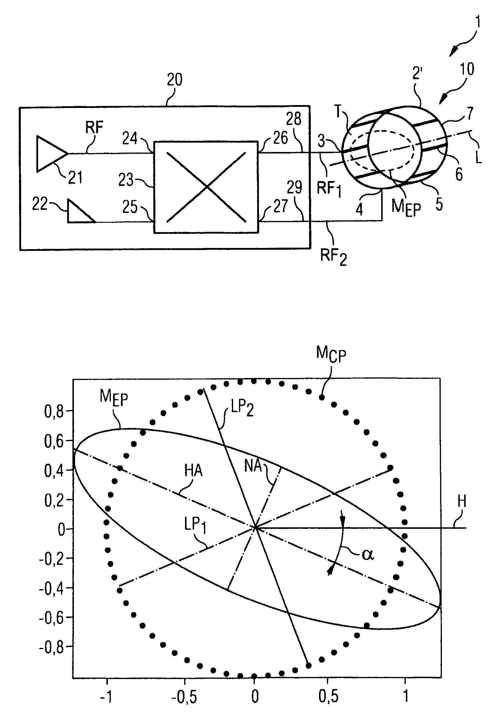
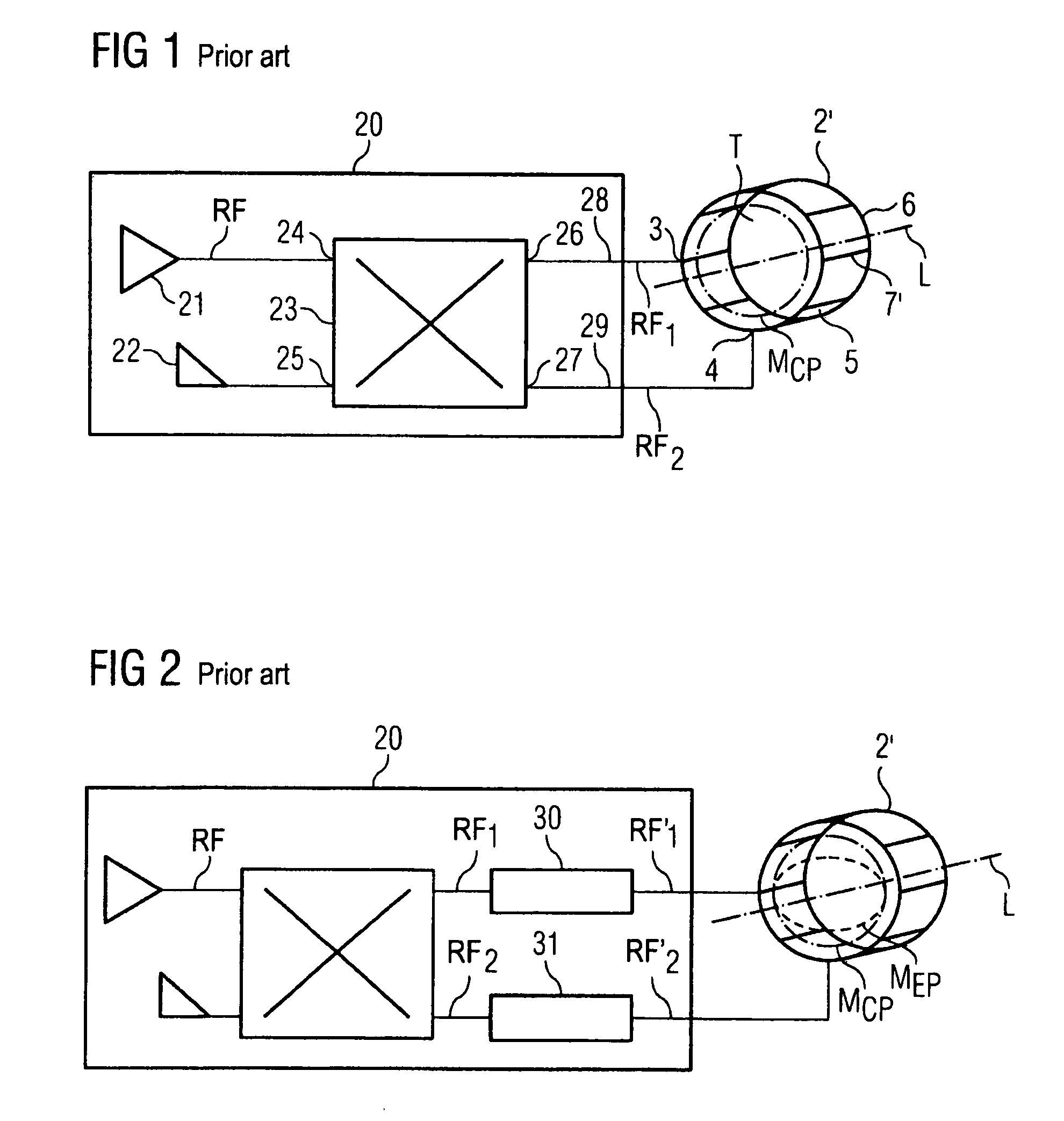
[0042]FIGS. 1 and 2 were already explained in detail above. The exemplary prior art embodiment according to FIG. 1 is a typical, presently used whole-body antenna with a cage structure which is supplied by a typical radio-frequency supply device 20. This radio-frequency supply device 20 is fashioned so that the phase ratio between the partial signals RF1, RF2 is established at exactly 90° and the amplitudes are identical within the scope of the typical tolerances. Only a circularly polarized radio-frequency field is ever emitted with this transmission system in the unloaded state of the whole-body antenna 2′.

[0043]FIG. 2 shows a more variable exemplary embodiment for a transmission system in which the ratio of the amplitudes and / or phases of the two partial signals RF1′, RF2′ can be freely adjusted relative to one another by means of amplitude and / or phase regulators 30, 31, whereby different transmission modes MCP, MEP can be emitted in the whole-body antenna 2′.

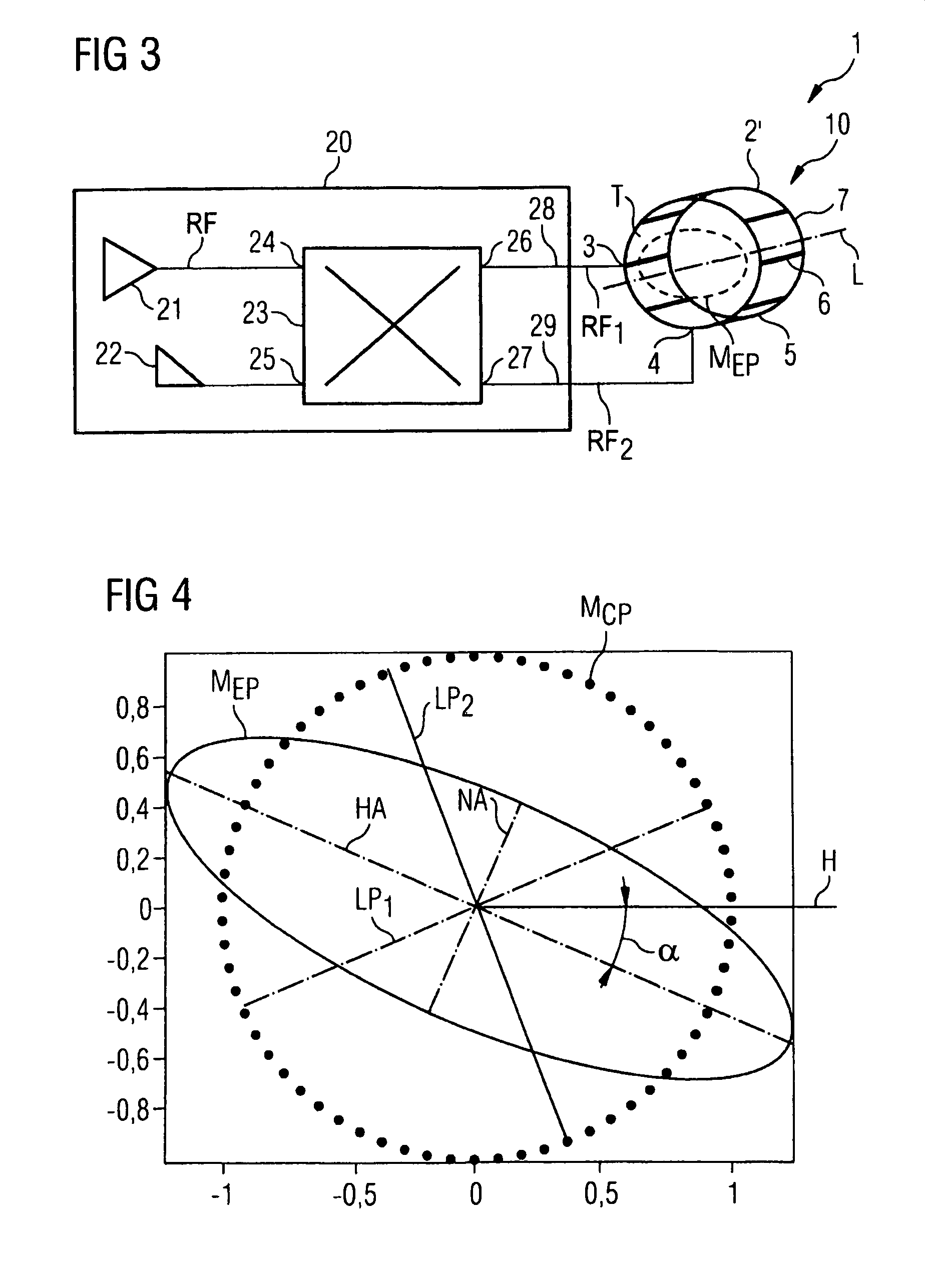
[0044]FIG. 3 now sh...


PUM

PropertyMeasurementUnit
non-zero angleaaaaaaaaaa

Abstract

A magnetic resonance system obtaining magnetic resonance exposures of an examination subject, has an examination tunnel, a whole-body antenna with two connection terminals. The whole-body antenna cylindrically extends around the examination tunnel along a longitudinal axis. The system has a radio-frequency supply device in order to respectively supply the whole-body antenna with radio-frequency signals for emission of a radio-frequency field in the examination tunnel. The radio-frequency supply device has a radio-frequency generator for generation of a radio-frequency signal, a signal splitter that divides a radio-frequency signal coming from the radio-frequency generator into two partial signals that are phase-shifted by 90° relative to one another. Two radio-frequency feed lines are connected with the two connection terminals of the whole-body antenna. Via these radio-frequency feed lines, the two partial signals are fed into the whole-body antenna. The whole-body antenna has an intrinsic transmission characteristic such that a radio-frequency field is emitted that is elliptically polarized in a defined manner in a plane lying perpendicular to the longitudinal axis (at least in the unloaded state of the examination tunnel).

Description

BACKGROUND OF THE INVENTION[0001]1. Field of the Invention[0002]The invention concerns a magnetic resonance system of the type having an examination tunnel and a whole-body antenna with two connection terminals that extends like a cylinder around the examination tunnel along a longitudinal axis, and a radio-frequency supply device in order to respectively supply the whole-body antenna with radio-frequency signals for emission of an radio-frequency field in the examination tunnel. The radio-frequency supply device has a radio-frequency generator for generation of a radio-frequency signal, a signal splitter that splits a radio-frequency signal (arriving from the radio-frequency generator) to be emitted into two partial signals that are phase-shifted by 90° relative to one another, and two radio-frequency feed lines connected with the two connection points of the whole-body antenna, via which radio-frequency feed lines the two partial signals are fed into the whole-body antenna. Moreov...

Claims


Application Information

Patent Timeline
Patent Type & Authority Patents(United States)
IPC IPC(8): G01V3/00A61B5/055
CPCG01R33/34046G01R33/3415G01R33/5659G01R33/3678Y10T29/49016
Inventor NISTLER, JUERGENRENZ, WOLFGANGSPECKNER, THORSTEN
Owner SIEMENS HEALTHCARE GMBH
Why Eureka
Try Eureka