Zone melting furnace thermal field with dual power heating function and heat preservation method

a heating function and thermal field technology, applied in the field of semiconductor manufacturing, can solve the problems of affecting production efficiency and equipment damage, difficult to adjust the heating process of a single power supply, and uneven temperature distribution below the melting zon

Active Publication Date: 2017-10-24
ZHEJIANG JINGSHENG MECHANICAL & ELECTRICAL
View PDF15 Cites 0 Cited by
  • Summary
  • Abstract
  • Description
  • Claims
  • Application Information

AI Technical Summary

Benefits of technology

[0017]the thermal field with the dual power heating function is adopted in the production of zone-melted silicon single crystals, wherein the primary heating power supply generates heat by means of the eddy current of the primary heating coil to realize heating and melting of the polycrystalline rod, and the auxiliary heating power supply carries out thermal field adjustment on the single crystal rod below a melting zone by means of the auxiliary heater, so that the temperature distribution of the single crystal rod can be accurately controlled. The present invention can solve the problem of single crystal rod cracking caused by unreasonable distribution of the thermal field and overlarge thermal stress in the growth process of the large-diameter zone-melted silicon single crystals over 6.5 inches, and simultaneously can improve the thermal field distribution in the growth process of 3-6 inch zone-melted silicon single crystals, solve the problem of broken ridges caused by unreasonable distribution of the thermal field and overlarge thermal stress, improve the productivity of the silicon single crystals to over 85% from 70% in the existing technology and enhance the quality of the silicon single crystals.

Problems solved by technology

By the adoption of float zone melting, the thermal field is concentrated near the melting zone, and the temperature distribution below the melting zone is not uniform.
With the increase of the diameter of the single crystal rod, the melting zone area and the thermal stress are increased in a geometric level, and when the thermal stress of the single crystal rod is larger than its critical shear pressure, the single crystal rod shifts to cause broken ridges, and even rupture to further affect the production efficiency and damage equipment.
In the existing technology, all large-diameter zone-melted single crystal silicon over 6.5 inches faces to the problem of single crystal rod cracking owing to unreasonable distribution of the thermal field and overlarge thermal stress, and broken ridges caused by unreasonable distribution of the thermal field and overlarge thermal stress in the growth process of 3-6 inch zone-melted single crystal silicon are one of the most major problems for improving the productivity of the silicon single crystals.
It is difficult to adjust the heating process of a single power supply, and is especially difficult to control the thermal field distribution of a single crystal rod below the primary heating coil.
However, the copper heat preservation ring device can only reflect the heat irradiated from the melting zone passively, and thus the reflected heat is uncontrollable in size and position.
PRC (Disclosure) patents CN 102808216 A, CN102321913 A, CN102358951 A, CN202492612U and the like disclose a thermal field structure employing such primary heating ring and such heat preservation ring respectively, and different materials are also adopted for heat preservation in the disclosed technologies, however, these heat preservation devices employ passive heat preservation, are difficult to control and thus are inapplicable to growth of large-diameter zone-melted monocrystalline silicon.

Method used


Image

  • Zone melting furnace thermal field with dual power heating function and heat preservation method
  • Zone melting furnace thermal field with dual power heating function and heat preservation method
  • Zone melting furnace thermal field with dual power heating function and heat preservation method

Examples


Embodiment Construction

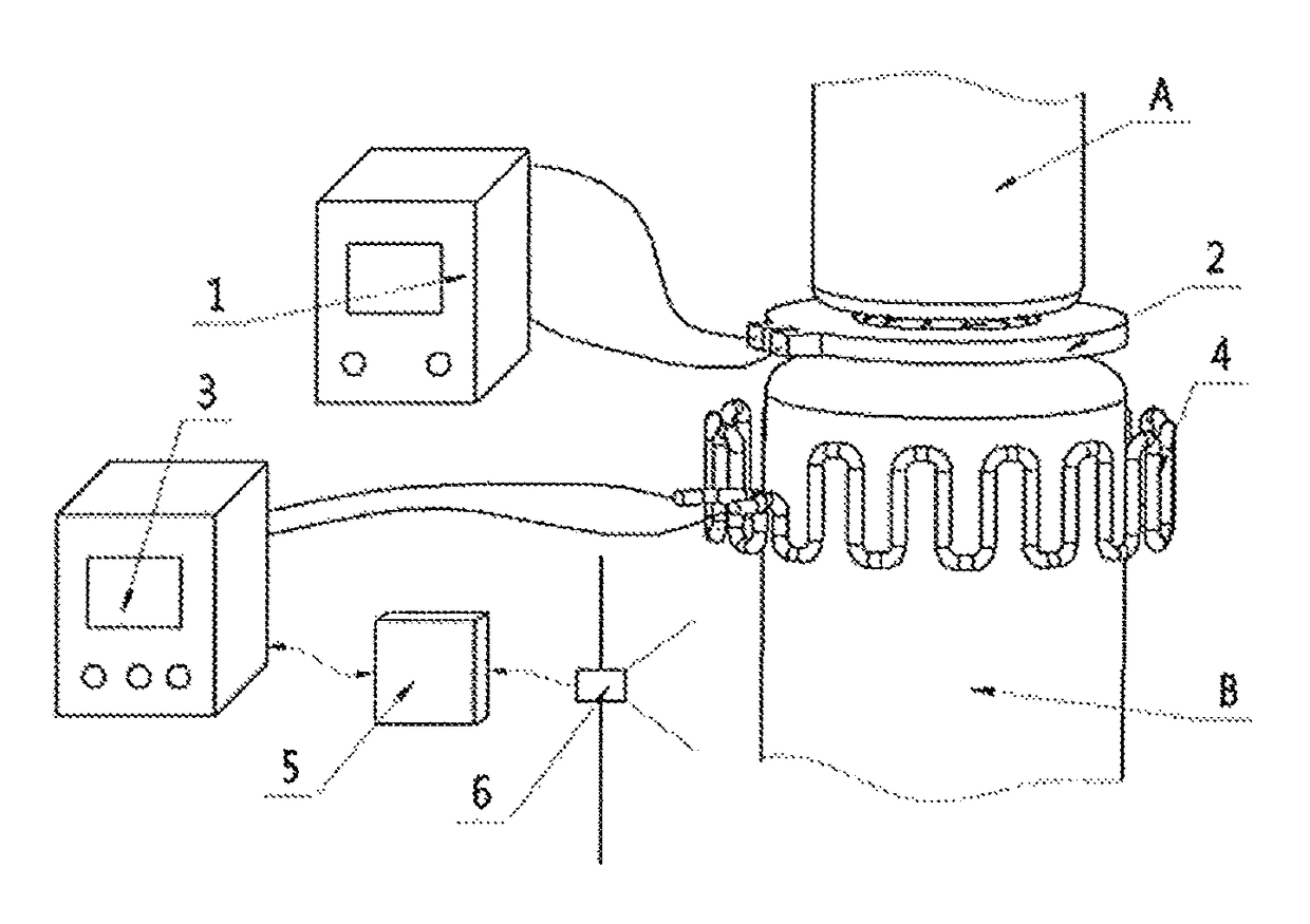
[0022]It needs to be first illustrated that the application of an automatic control technology and a computer technology will be involved in the realization process of the present invention. The applicant holds that the present invention can be realized completely after reading the application document carefully and accurately understanding the realization principle and the invention objective of the present invention. For example, the data analysis module 5 can employ a PLC (Programmable Logic Controller) with an optional model CJ2M produced by OMRON. Those skilled in the art can finish built-in control software by applying their software programming skills on the premise of combining the existing well-known technologies. Therefore, all contents mentioned by the application document of the present invention belong to this category, and the applicant will not enumerate one by one.

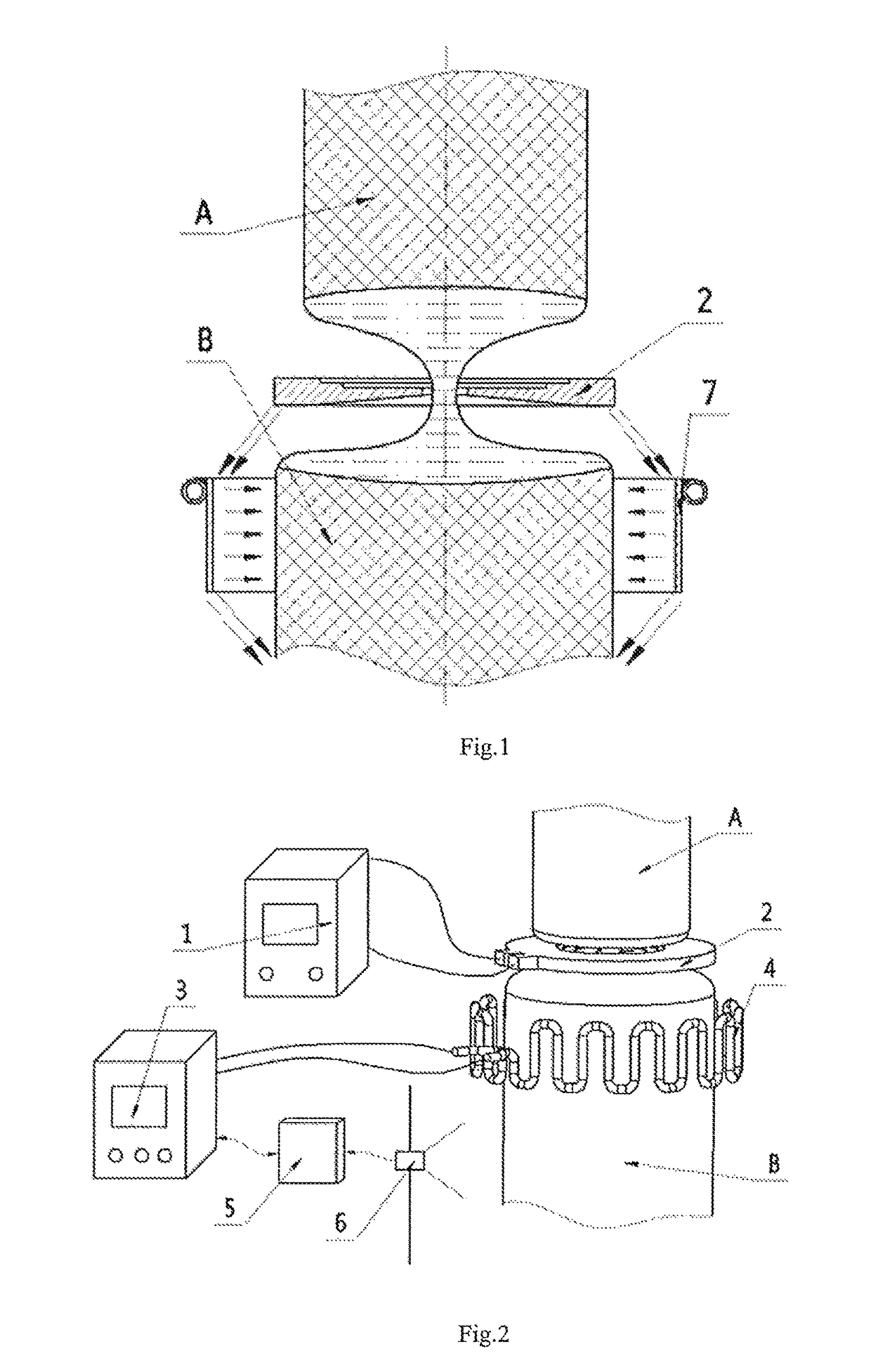
[0023]The preset invention will be further described in detail as below in conjunction with the attached...


PUM

PropertyMeasurementUnit
temperatureaaaaaaaaaa
diameteraaaaaaaaaa

Abstract

The present invention aims at providing a zone melting furnace thermal field with a dual power heating function and a heat preservation method. The zone melting furnace thermal field comprises a primary heating coil and an auxiliary heater, wherein the auxiliary heater has a wavy appearance bent repeatedly up and down and forms a circular loop by surrounding in the horizontal direction, wherein both end parts of the auxiliary heater are provided with ports and are connected with an auxiliary heating power supply through cables; and the auxiliary heating power supply is also sequentially connected with a data analysis module and an infrared temperature measuring instrument through single lines. The present invention can solve the problem of single crystal rod cracking caused by unreasonable distribution of the thermal field and overlarge thermal stress in the growth process of zone-melted silicon single crystals over 6.5 inches, and simultaneously can improve the thermal field distribution in the growth process of 3-6 inch zone-melted silicon single crystals.

Description

TECHNICAL FIELD[0001]The present invention relates to the field of semiconductor manufacturing, in particular to a zone melting furnace thermal field with a dual power heating function.BACKGROUND ART[0002]Silicon is a basic material in the primary industry, namely the electronic information technology industry throughout the world and accounts for over 95% of the use amount of semiconductor materials in the world. Zone-melted silicon single crystals have the advantages of high purity, good uniformity, few defects and the like owning to its unique growth mode and are thus applicable to high-power semiconductor components. With vigorous development of the electric and electronic industry, various novel electric and electronic devices, such as SR silicon rectifiers, SCR silicon-controlled rectifiers, GTR giant transistors, GTO thyristors, SITH static inductive thyristors, IGBT insulated gate bipolar transistors, PIN ultrahigh voltage diodes, smart power devices and power IC (Integrated...

Claims


Application Information

Patent Timeline
Patent Type & Authority Patents(United States)
IPC IPC(8): C30B13/18C30B29/06C30B13/20C30B13/28
CPCC30B13/18C30B29/06C30B13/28C30B13/20
Inventor CAO, JIANWEIOUYANG, PENGGENWANG, DANTAOFU, LINJIANCHEN, MINGJIESHI, GANGQIU, MINXIU
Owner ZHEJIANG JINGSHENG MECHANICAL & ELECTRICAL
Why Eureka
Try Eureka