
Flexural vibration piece and oscillator using the same

a technology of flexural vibration and oscillator, which is applied in the direction of device details, device material selection, piezoelectric/electrostrictive device details, etc., can solve the problems of difficult to realize a desired performance, difficult to form grooves or holes along with miniaturization, and difficult to achieve vibration energy loss. , to achieve the effect of stable oscillation characteristics

Inactive Publication Date: 2013-01-29
SEIKO EPSON CORP
View PDF9 Cites 1 Cited by
  • Summary
  • Abstract
  • Description
  • Claims
  • Application Information

AI Technical Summary

Benefits of technology

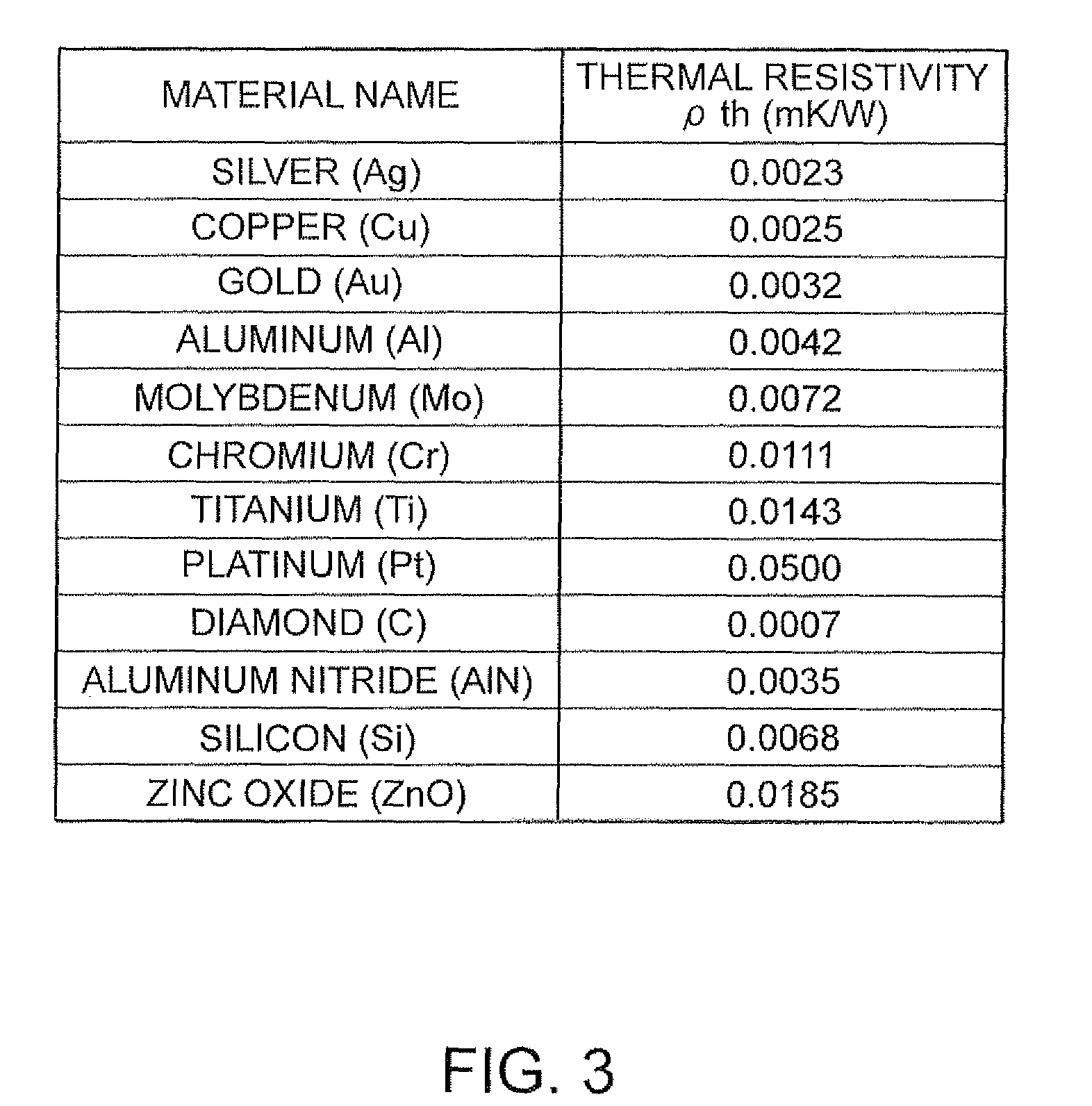
The present inventor has found that by setting the thickness of the heat conduction path based on the heat conduction coefficient between the flexural vibrator and the heat conduction path, and the number of heat conduction paths, heat conduction between two regions can be efficiently performed. This results in a reduction in thermal relaxation time and suppresses a decrease in Q value, leading to a small oscillator with stable oscillation characteristics.

Problems solved by technology

In addition to the mechanical vibration energy loss, vibration energy loss is also caused by heat conduction.
As a result, the Q value of the tuning fork-type quartz vibration piece 1 decreases to make vibration characteristics unstable, which makes it difficult to realize a desired performance.
However, in the tuning fork-type quartz vibration piece 1 disclosed in JP-UM-A-2-32229, it becomes difficult to form the grooves or holes along with miniaturization.
In addition, an effect of extending the thermal relaxation time due to the grooves or holes is reduced, which causes a problem that an effect of suppressing a reduction in Q value cannot be sufficiently provided.

Method used


Image

  • Flexural vibration piece and oscillator using the same
  • Flexural vibration piece and oscillator using the same
  • Flexural vibration piece and oscillator using the same

Examples


first embodiment

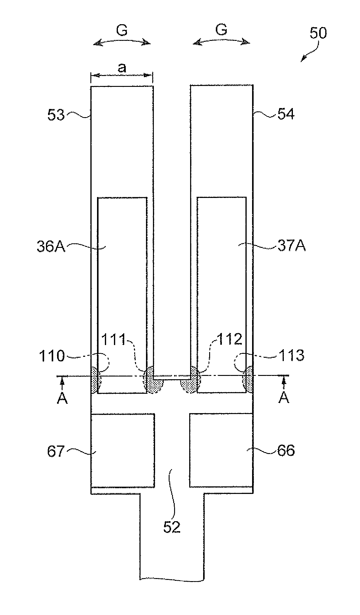
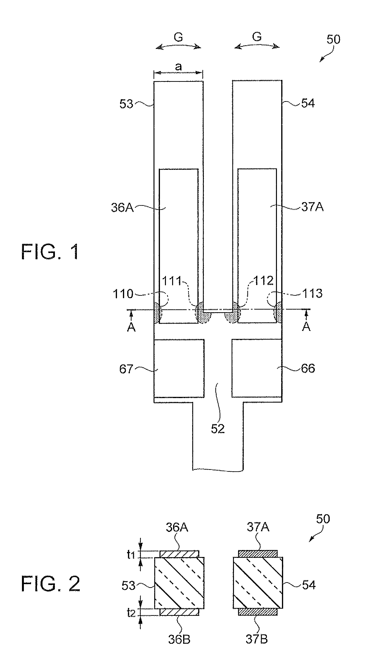
[0047]FIGS. 1 and 2 schematically explain a tuning fork-type quartz vibration piece as a flexural vibration piece of a first embodiment. FIG. 1 is a plan view of one main surface side. FIG. 2 is a cross-sectional view taken along line A-A in FIG. 1.

[0048]In FIG. 1, a tuning fork-type quartz vibration piece 50 of the embodiment is formed to have a so-called tuning fork-type external shape with a base 52 that is formed by processing a flexural vibrator material and a pair of vibration arms 53 and 54 bifurcated from one end side (an upper end side in the drawing) of the base 52 and extending in parallel to each other. As the flexural vibrator material, a material cut out from a single crystal of quartz is used in the embodiment in the same manner as in a related-art tuning fork-type quartz vibration piece. For example, the material is formed from a so-called Z-cut quartz thin plate with the Y-axis of crystal axis of quartz being directed to a longitudinal direction of the vibration arm...

second embodiment

[0076]In the first embodiment, parts of the excitation electrodes 36A, 36B, 37A, and 37B of the tuning fork-type quartz vibration piece 50 are used as the heat conduction paths. This is not restrictive, and a heat conduction path may be disposed separately from the excitation electrode on the flexural vibrator.

[0077]FIGS. 4A and 4B schematically explain a tuning fork-type quartz vibration piece in which heat conduction paths are disposed separately from excitation electrodes on the flexural vibrator. FIG. 4A is a plan view of one main surface side, and FIG. 4B is a cross-sectional view taken along line B-B in FIG. 4A. In FIGS. 4A and 4B of a second embodiment, the same constituent as in the first embodiment is denoted by the same reference numeral, and the description thereof is omitted.

[0078]In FIG. 4A, a tuning fork-type quartz vibration piece 150 of the second embodiment has a tuning fork-type external shape with the base 52 formed of a flexural vibrator material and the pair of ...


PUM


Abstract

A flexural vibration piece including a vibrator having a first region on which a compressive stress or a tensile stress acts and a second region on which a tensile stress acts when a compressive stress acts on the first region and a compressive stress acts when a tensile stress acts on the first region, and performs flexural vibration in a first plane; and a heat conduction path formed of a material having a thermal conductivity higher than the vibrator and that thermally connects the regions, wherein when m is the number of heat conduction paths, ρth is the thermal resistivity of the heat conduction path, ρv is the thermal resistivity of the vibrator, tv is the thickness of the vibrator in a direction orthogonal to the first plane, and tth is the thickness of the heat conduction path, a relationship of tth≧(1 / m)×tv×(ρth / ρv) is satisfied.

Description

BACKGROUND[0001]1. Technical Field[0002]The present invention relates to a flexural vibration piece that vibrates in a flexural mode and an oscillator using the same.[0003]2. Related Art[0004]As a flexural vibration piece that vibrates in a flexural mode in the related art, a tuning fork-type flexural vibration piece has been widely used in which a pair of vibration arms are extended in parallel to each other from a base formed of a base material for a flexural vibrator, such as a piezoelectric material for example, and the vibration arms are caused to horizontally vibrate toward each other and away from each other. When the vibration arms of the tuning fork-type flexural vibration piece are excited, the occurrence of the vibration energy loss causes a reduction in performance of the vibration piece, such as an increase in CI (Crystal Impedance) value or a reduction in Q value. For preventing or decreasing such a vibration energy loss, various measures have been taken in the related...

Claims


Application Information

Patent Timeline
Patent Type & Authority Patents(United States)
IPC IPC(8): H03H9/21H01L41/04H01L41/09H01L41/12H01L41/18H01L41/187H01L41/22H01L41/29H03H9/19H03H9/215
CPCH03H9/215
Inventor FURUHATA, MAKOTOYAMADA, AKINORIHAMAYAMA, YUJI
Owner SEIKO EPSON CORP
Learn More