Contact arrangement

a contact arrangement and electrically conductive technology, applied in the direction of coupling contact members, coupling device connections, fixed connections, etc., can solve the problems of high cost, high cost, and high cost of contact arrangements, and achieve cost-effective manufacturing, large quantities, and simple stamping

Active Publication Date: 2013-02-05
ITT MFG ENTERPRISES LLC
View PDF5 Cites 6 Cited by
  • Summary
  • Abstract
  • Description
  • Claims
  • Application Information

AI Technical Summary

Benefits of technology

[0007]As a result of the measures according to the present invention, an electrically conductive contact arrangement is created, which can be manufactured in a simple manner by placing spring fork contacts in a row and which can be adjusted to the relevant, or calculated, maximum current transmission power. Thus planar spring fork contacts may be manufactured cost-effectively, for example, as a simple stamping part and in large quantities. The same applies to assembling and holding together this multiplicity of planar spring fork contacts on one carrier and connecting it to a connecting unit. As a result of this way of assembling planar. i.e., plate-shaped, spring fork contacts, the geometry of these contacts may be easily adjusted to the requirements of specific applications, and also with respect to the mating contact. The characteristics of the spring fork contacts are relatively easy to model in one plane due to the planar quality of the component.
[0009]Manufacturing methods using roller burnishing yield the massive composite, whereby the connecting points may be gas-tight and cold-welded so that the lowest transition resistances may be achieved.
[0015]The connecting unit may be provided as a crimped element or as a screw element for the relevant conductor or conductors. In addition, by providing two or more connecting elements, division into two or more terminals is advantageously possible at high current levels.
[0017]A blade contact unit that fits with the fork-shaped spring contact unit is also advantageously configured so as to be planar and plate-shaped, whereby depending on the installation space, the connecting unit may be arranged so as to be perpendicular or transverse with respect to the insertion direction of the blade contact. This planar, plate-shaped configuration provides the option of inserting the blade contact into the female contact device both from the end face as well as longitudinally. This is advantageous for use in the most varied kinds of configurations of plug-in connectors. The design as a right-angled contact is advantageous in applications in which the users during operation must be protected with shock hazard protection and / or figure protection; the relevant grip opening is never much larger than the material thickness of the blade contact.
[0018]As a flat component, the blade contact is easy to modify. Various cutouts in the contact area are possible, on the basis of which the plug-in process may be further optimized by sliding the spring forks serially. This provides for a further reduction in the plug-in forces and support for a gentle insertion of the blade contact into the spring fork contacts.
[0020]The blade contact unit may be manufactured in a simple manner.

Problems solved by technology

According to the prior art, in electrically conductive contact arrangements for high-performance applications, either contact units have been known that are manufactured with great geometric precision and are therefore expensive, or the contact arrangements have been provided with expensive, delicate spring contacts as supplemental parts.

Method used


Image

  • Contact arrangement
  • Contact arrangement
  • Contact arrangement

Examples


Embodiment Construction

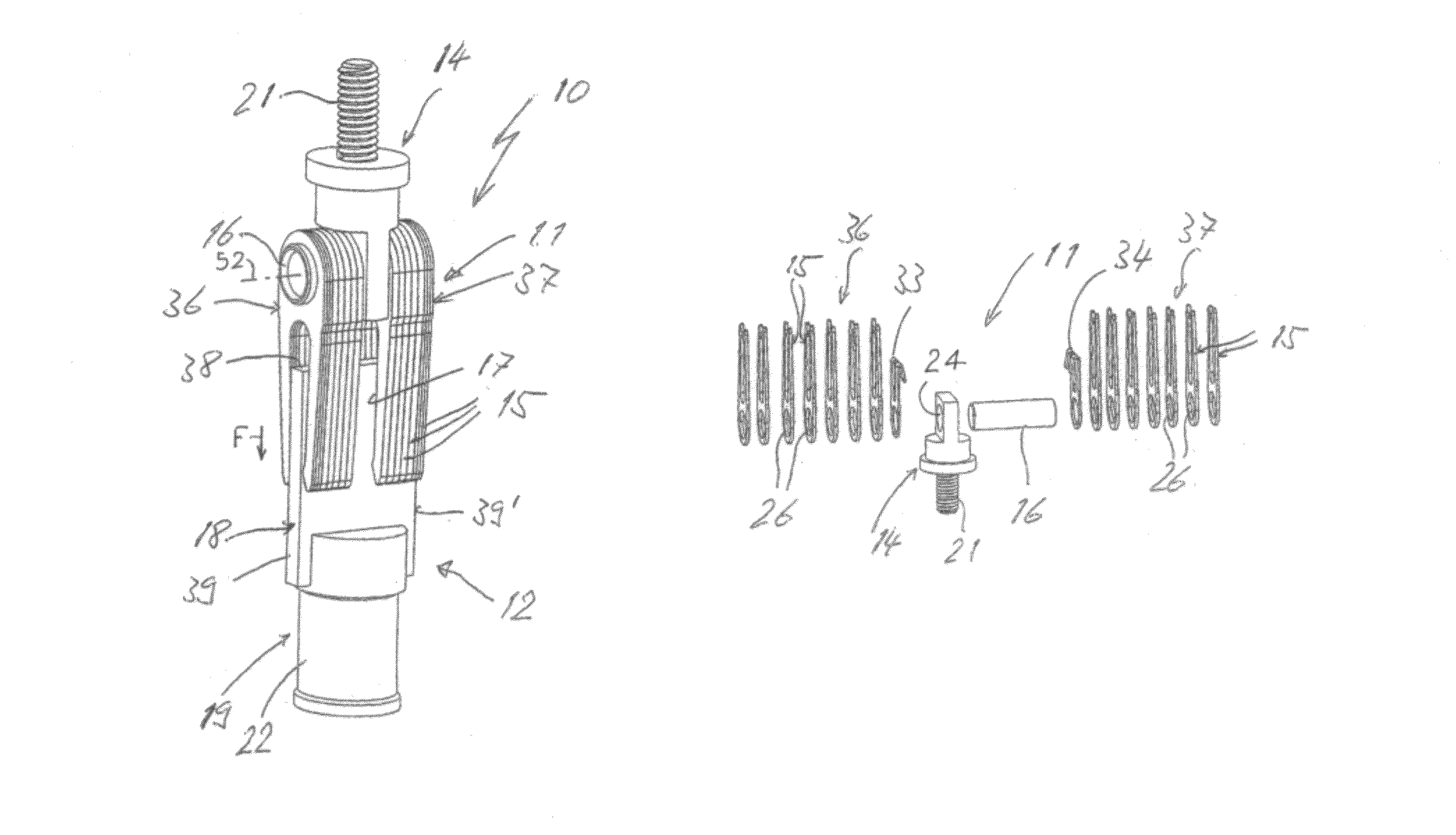
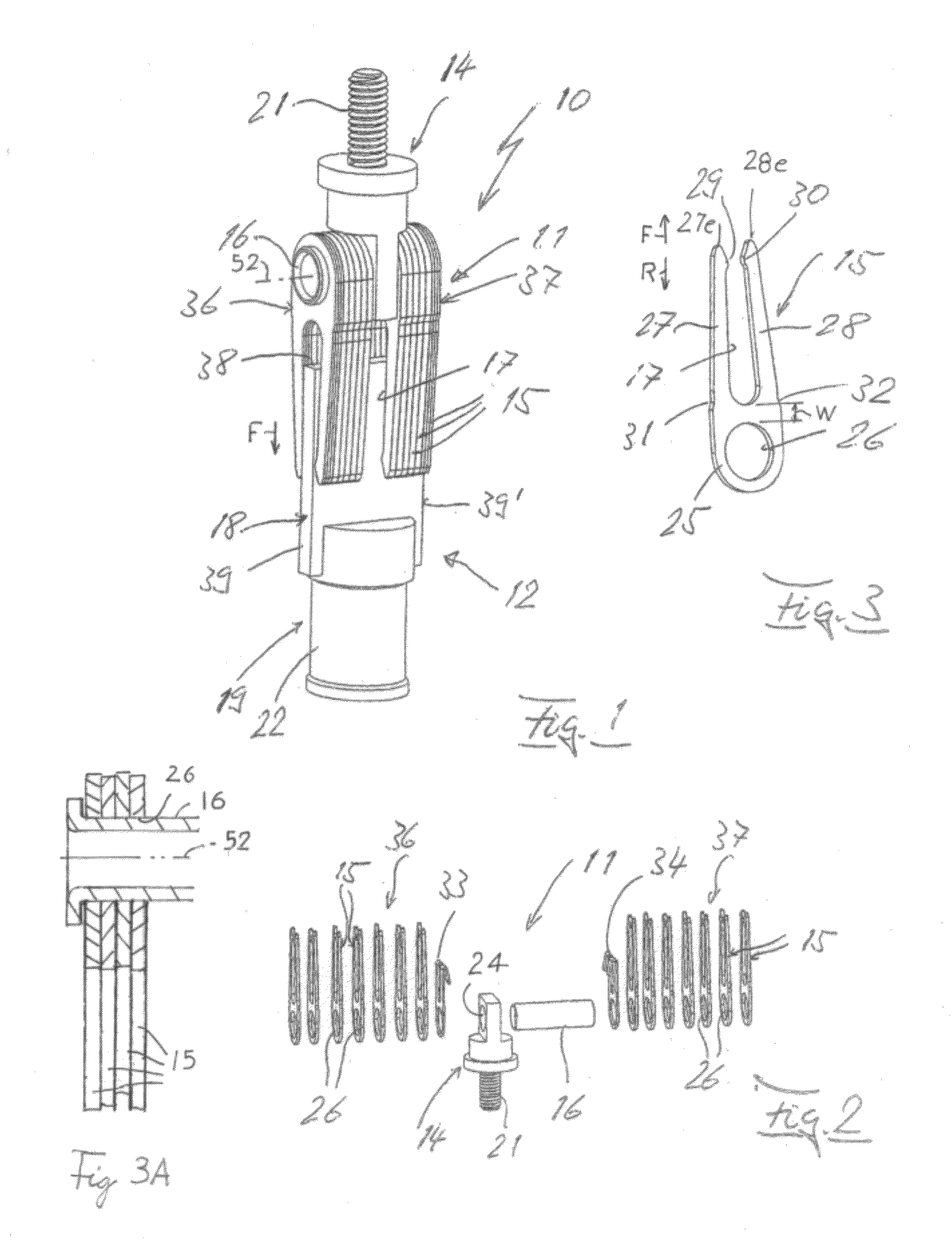
[0034]FIG. 1 shows an electrically conductive contact arrangement 10 for plug-in connections handling high transmission power, as is the case with electrically operated motor vehicles, for example. The contact arrangement includes a fork-shaped spring contact unit 11 and a blade contact unit 12 that are connected together. Spring contact unit 11 has a multiplicity of planar, plate-shaped spring fork contacts 15, or fork contacts, which are strung on a shaft 16 in the form of a tubular carrier 16, and has a connecting unit 14 that is also connected to the carrier. The fork contacts extend along a stack axis 52.

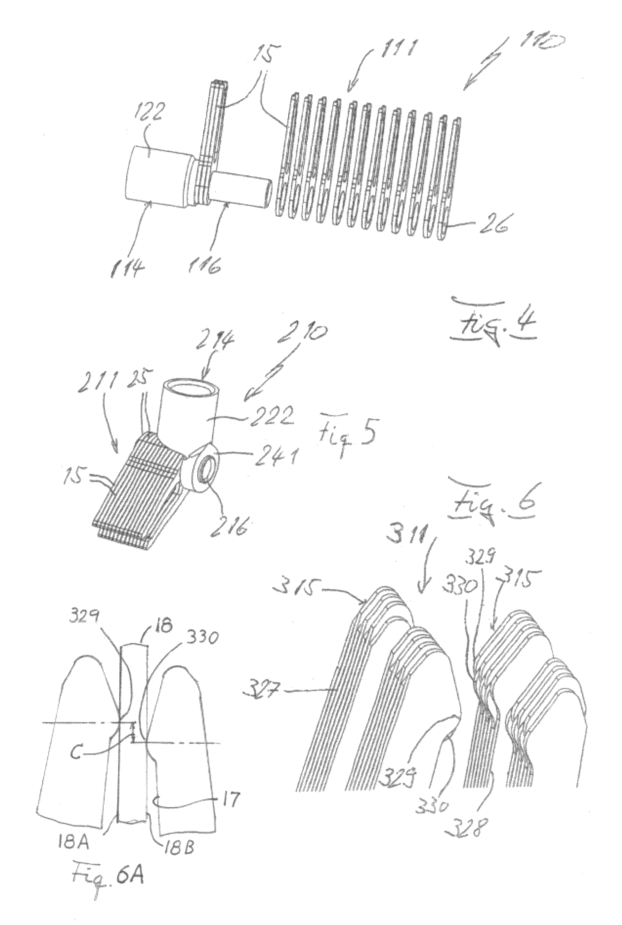
[0035]Blade contact unit 12 has a planar, plate-shaped blade contact 18 which has electrically conductive opposite faces 18A, 18B (FIG. 6A). Each fork contact forms a slot 17 (FIG. 3) and each fork contact 15 resiliently engages the blade contact opposite faces. A connecting unit 19 (FIG. 1), is electrically connected to blade contact 18. Connecting unit 14 is provided with for...


PUM


Abstract

A contact arrangement (10) comprising fork-shaped contacts (15) that engage opposite faces of a blade contact (18). For good heat dissipation together with low transition resistance, the contact arrangement is made up of multiple planar, i.e., plate-shaped, fork contacts (15), which are supported and connected to each other on a shaft-like carrier (16) that is joined to a perpendicular connecting unit (14).

Description

CROSS-REFERENCE TO RELATED APPLICATION[0001]Applicant claims priority from German patent application no. 10 2010 044 612.2 filed Sep. 1, 2010.BACKGROUND OF THE INVENTION[0002]The present invention relates to an electrically conductive contact arrangement.[0003]In electrically conductive contact arrangements in systems of high specific power density, it is essential, on the one hand, to keep the Joule heating small through having minimal thermal resistances of the contact units that are to be, or have been, connected to each other, and, on the other hand, to remove the residual heat through good heat dissipation into other current-carrying components. In this context, the decisive parameters are selecting materials for the contact units along with their coatings, having the greatest possible number of contact points, determining the magnitude of the contact forces compatible with reasonable ease of operation, and ensuring the largest possible masses and cross-sections in the contact ...

Claims


Application Information

Patent Timeline
Patent Type & Authority Patents(United States)
IPC IPC(8): H01R39/00
CPCH01R13/112H01R13/113H01R12/55H01R2101/00
Inventor LITTEK, MARTINSCHREMMER, ANDREAS MICHAELHAGMANN, BERNDBIHRER, MARCUS
Owner ITT MFG ENTERPRISES LLC
Why Eureka
Try Eureka