Ground peg, and device and method for the production thereof

a technology for ground pegs and steel tubes, which is applied in the direction of resistive welding apparatus, bulkheads/piles, domestic objects, etc., can solve the problems of pegs often reaching the limits of their strength, the production of the entire ground peg turns out to be very labor-intensive and thus relatively expensive, and the pegs are often jammed or locked. , to achieve the effect of suitably increasing the rotational speed of the steel tub

Active Publication Date: 2013-02-05
KRINNER INNOVATION
View PDF12 Cites 3 Cited by
  • Summary
  • Abstract
  • Description
  • Claims
  • Application Information

AI Technical Summary

Benefits of technology

[0009]It is an object of the present invention to create a ground peg that can be produced very efficiently and inexpensively, and to put forward a method to produce said ground peg. In this context, as many manufacturing steps as possible should be automated or partially automated, that is to say, these manufacturing steps should be performed with as little manual labor as possible. Another objective of the invention is to put forward an especially high-strength ground peg that is particularly well-suited for use in hard subsoil. Finally, a third objective of the invention is to put forward a simply structured device for the production of such a ground peg so as that it can be manufactured quickly and inexpensively.

Problems solved by technology

In the case of minor dimensional deviations, this can easily result in jamming or locking of the thread.
The welding of the external thread is normally done by hand, and so are most of the other production steps, for example, the welding of the two tube sections of the ground peg, so that the production of the entire ground peg turns out to be very labor-intensive and thus relatively expensive.
Another problem can occur due to the multi-component structure and thus the resultant weakening in the vicinity of the weld seam.
In the case of very rocky and hard subsoil, however, these ground pegs often reach the limits of their strength, and they tend to fail due to breakage, especially in the area where the cylindrical tube section is joined to the kneaded conical section.
Consequently, the conical section does not yield under high loads, but rather, it is especially torsionally stiff.
However, on the other hand, since the conical section is subjected to the greatest torsional loads while the ground peg is being screwed into very hard subsoil, this load is almost completely transmitted to the upper area and to the weld seam, so that the latter tends to crack under very high loads.

Method used


Image

  • Ground peg, and device and method for the production thereof
  • Ground peg, and device and method for the production thereof
  • Ground peg, and device and method for the production thereof

Examples


Embodiment Construction

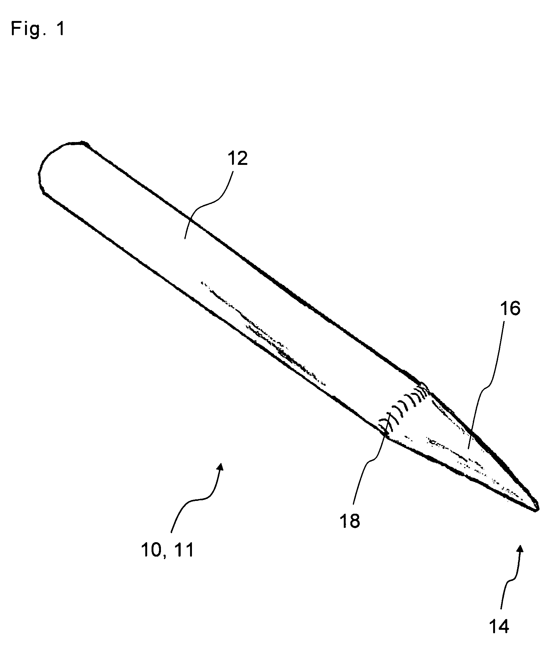
[0038]The schematic depictions in FIGS. 1 and 2 each show perspective views of a preliminary production stage of a ground peg 10 which is made from a steel tube 11, and which comprises an upper cylindrical section 12 and a lower section 16 that tapers downwards to form a tip 14, and an external thread—not yet applied here—that extends along at least a part of the lower section after it has been applied onto the ground peg 10. In the first variant according to FIG. 1, the upper section 12 and the lower section 16 are formed from two parts that are joined in a ring-shaped weld seam 18. In this variant, the lower section 16 is normally produced by kneading a previously cylindrical steel tube that, in this process, is compacted and shaped to form a generally conical section with a closed tip 14.

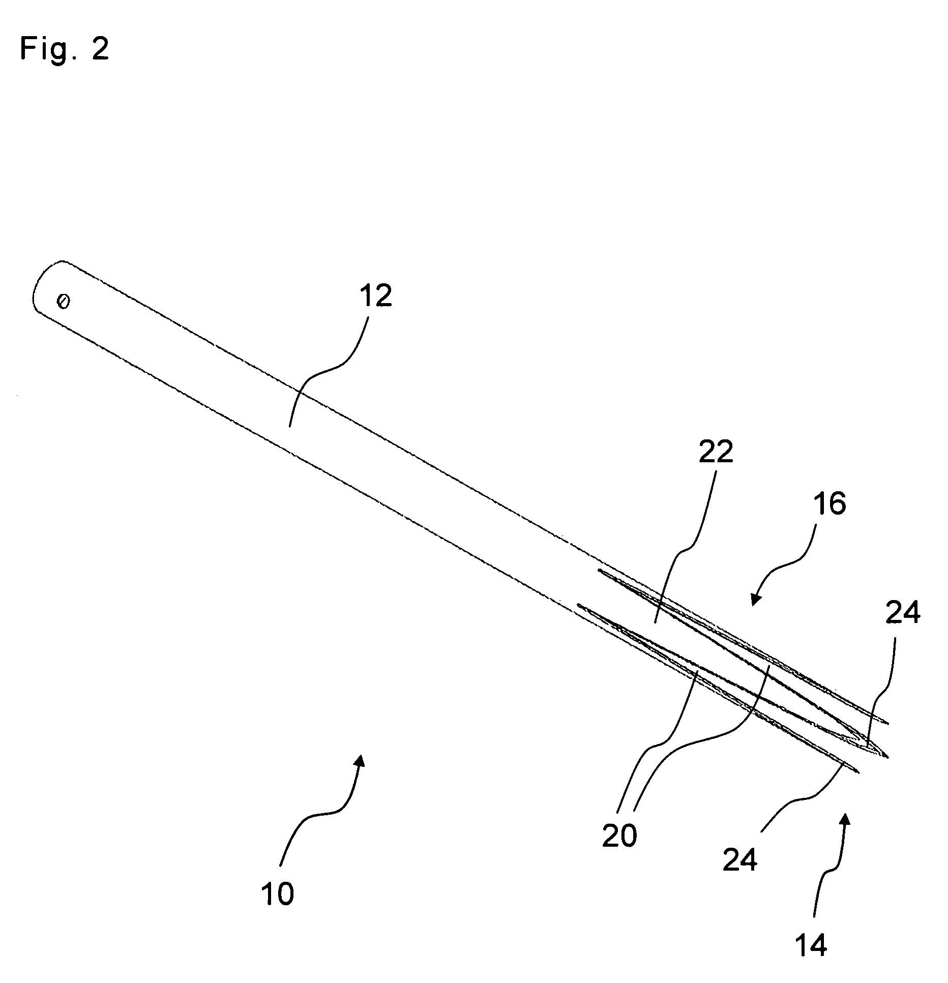
[0039]In the second variant according to FIG. 2, the upper section 12 and the lower section 16 are made in one piece from a single contiguous steel tube section 11. In the embodiment shown, the l...


PUM

PropertyMeasurementUnit
wall thicknessaaaaaaaaaa
diameteraaaaaaaaaa

Abstract

The invention relates to a ground peg (10) which is made from a steel tube (11) and comprises an upper cylindrical section (12), a lower section (16) that tapers towards the bottom to form a tip (14), and an external thread (26) that extends along at least part of the lower section (16) and is formed from a continuous sheet metal strip (28) welded onto an external surface (32) of the ground peg (10) by means of a continuous or regularly interrupted fillet weld (34). The external thread (26) has a nearly constant pitch (S) and slope (a) relative to a longitudinal axis (40) of the ground peg (10) along the entire length of the external thread (26). The invention further relates to a method or producing such a ground peg (10). In said method, the external thread (26) is laterally fed to the external surface (32) of the rotating steel tube as an elongate sheet metal strip (28) and is welded onto said external surface (32), the steel tube (11) being moved relative to the feeding point of the sheet metal strip (28) at a regular advance (V) in the longitudinal direction of the steel tube (11). The invention finally relates to a device for producing such a ground peg (10). Said device comprises a mechanism for clamping and rotating the steel tube as well as a mechanism (44) for feeding the sheet metal strip (28) to the external surface (32) of the steel tube (11) such that the sheet metal strip (28) tangentially rests there against.

Description

[0001]The present invention relates to a ground peg as well as to a method for the production of such a ground peg. The invention also relates to a device for the production of such a ground peg.BACKGROUND[0002]Ground pegs serve to anchor objects such as columns or support frames in the ground. Thus, for example, solar collectors outdoors are often anchored in the ground with such ground pegs.[0003]Such ground pegs exist in numerous different versions and dimensions. They normally consist of a tube section that has a constant diameter over a certain length. The lower section of the ground peg is conically tapered so that the ground peg can be screwed into the ground and can thus be firmly secured by displacing the soil. In order for the ground peg to be screwed in, it is provided with an external thread that can be formed, for example, by a welded-on sheet metal strip.[0004]The conical section is normally welded onto the cylindrical section. The conical section is usually made out o...

Claims


Application Information

Patent Timeline
Patent Type & Authority Patents(United States)
IPC IPC(8): B23K9/032F16M13/00
CPCE04H12/2215E02D5/801E04H12/2223
Inventor RAINER, STEPHAN
Owner KRINNER INNOVATION
Why Eureka
Try Eureka