
Device and method for unilateral lung ventilation

a technology of lung ventilation and device, applied in the field of lung ventilation, can solve the problems of trauma to the epithelial lining of the airway, adversely altering the mechanics, and each tube design has specific limitations

Inactive Publication Date: 2013-02-19
THE NEMOURS FOUND
View PDF19 Cites 13 Cited by
  • Summary
  • Abstract
  • Description
  • Claims
  • Application Information

AI Technical Summary

Benefits of technology

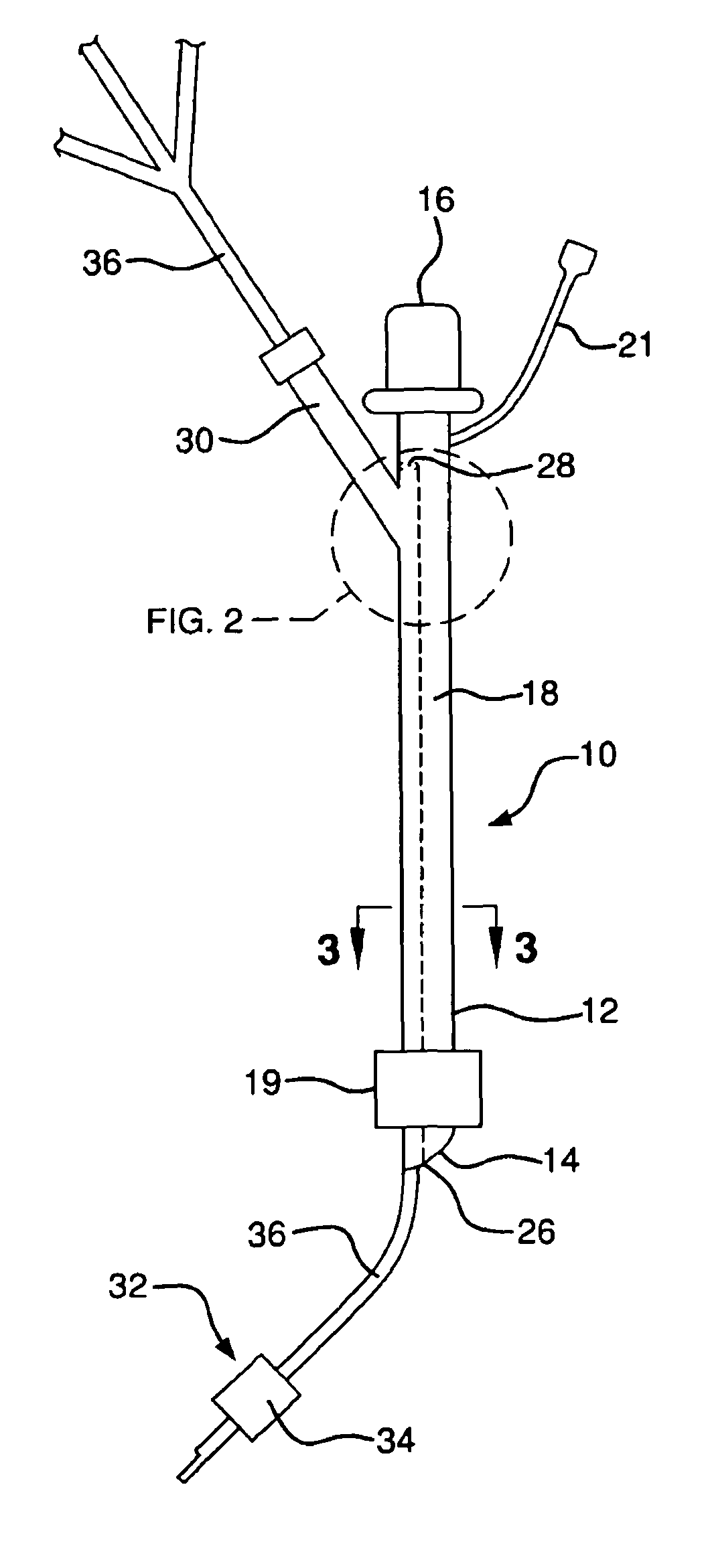
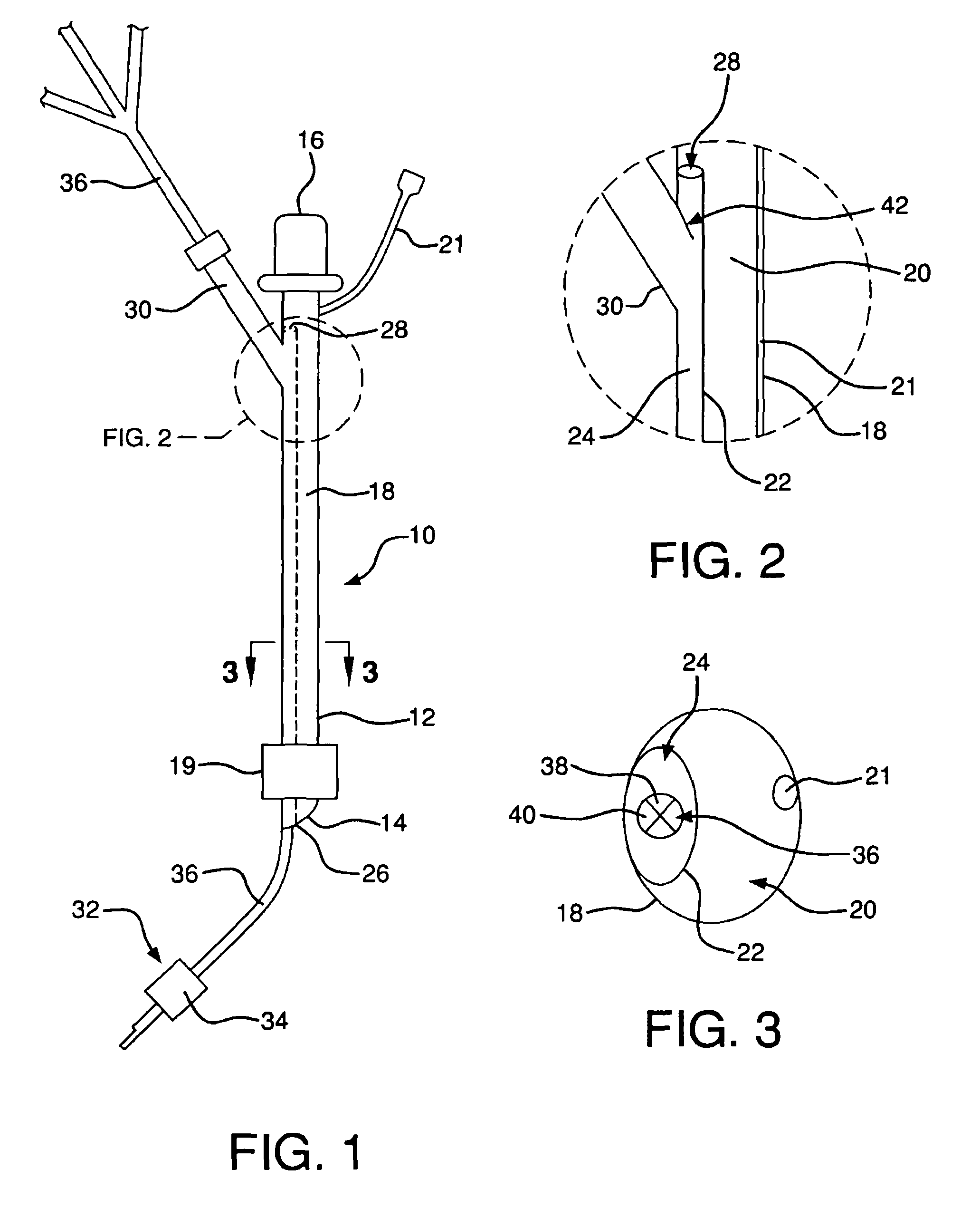
[0007]According to one aspect of the invention, a system for unilateral lung ventilation comprising an endotracheal tube and a blocking device. According to one exemplary embodiment, the endotracheal tube includes a main channel for delivering a ventilating gas to the trachea of a patient. The blocking device includes an inflatable member having inflated and deflated conditions and adapted for inflation within the mainstem bronchus of a non-ventilated one of a patient's lungs such that the ventilating gas from the endotracheal tube is prevented from entering the non-ventilated lung. The blocking device also includes an elongated catheter supporting the inflatable member and having an inflation lumen adapted to deliver a gas / fluid volume to the inflatable member. The catheter further includes at least one lung treatment lumen adapted for delivery of a treatment agent into the non-ventilated lung when the inflatable member is inflated within the mainstem bronchus of the non-ventilated lung.
[0008]According to another exemplary embodiment, the endotracheal tube has a primary wall defining a main channel for delivering a ventilating gas to the trachea of a patient and a secondary wall defining an inner channel located within the main channel. The blocking device includes an inflatable member having inflated and deflated conditions and adapted for inflation within the mainstem bronchus of a non-ventilated one of the lungs of the patient such that the ventilating gas from the endotracheal tube is prevented from entering the non-ventilated lung. The blocking device also includes an elongated catheter supporting the inflatable member and adapted to deliver a gas / fluid volume to the inflatable member. The inner channel of the endotracheal tube is adapted to receive the catheter and the inflatable member when the inflatable member is in the deflated condition to define a guideway to facilitate passage of the catheter and the inflatable member to a distal end of the endotracheal tube.
[0009]The endotracheal tube may also include a side branch connected to a primary wall of the endotracheal tube that defines the main channel. The side branch is adapted for receipt of the catheter and the inflatable member of the blocking device to direct the catheter and the inflatable member into the inner channel of the tube. The endotracheal tube may also include a valve adjacent a junction between the side branch and the primary wall adapted to substantially close an end of the side branch at the junction when the blocking device is removed from the inner channel. The closure of the side branch in this manner facilitates parallel flow of a ventilating gas through the endotracheal tube in both the main channel and the inner channel of the tube when the blocking device is removed from the endotracheal tube. When the blocking device is in place, the valve system will close to the top of the side channel, isolating the catheter suspending the blocking device from the warm ventilating gas being delivered through the main orifice of the endotracheal tube.

Problems solved by technology

However, each of these tube designs has specific limitations.
When the procedure is completed and the patient is restored to bilateral ventilation, the presence of the two fixed channels undesirably limits airflow in and out of the lung by increasing resistance, thus adversely altering the mechanics.
However, repeated intubations are known to result in trauma to the epithelial lining of the airways.
However, the passage of the balloon catheter through the standard endotracheal tube places the catheter within the main lumen of the standard tube, thereby disrupting laminar airflow in the main lumen.
This movement of the catheter contributes to the need for periodic repositioning of the balloon in the blocked bronchus, which can be a source of trauma to the epithelial tissues.
Furthermore, the catheter accessing the non-ventilated lung is not thermally isolated from the main orifice of the endotracheal tube, which can be a limitation for a potential therapy to be described herein.
Moreover, it is difficult to maintain arterial oxygen saturation because of the extreme ventilation / perfusion (V / Q) mismatch that results when one lung receives no ventilation.
Such high oxygen levels, however, are known contributors to lung disease.
Laboratory studies indicate that lung function is hampered following re-recruitment of a collapsed lung after only 30 minutes of unilateral lung ventilation.

Method used


Image

  • Device and method for unilateral lung ventilation
  • Device and method for unilateral lung ventilation

Examples


Embodiment Construction

[0015]Referring to the drawings, where like numerals identify like elements, there is shown in FIGS. 1 through 3 a system 10 for unilateral lung ventilation according to an exemplary embodiment of the invention. As described below in greater detail, the system 10 provides for blockage of a non-ventilated lung during ventilation of the other lung while simultaneously permitting delivery of therapeutic agents into the non-ventilated lung via a thermally isolated catheter.

[0016]Referring to FIG. 1, the system 10 includes an endotracheal tube 12 having a distal end 14 and an opposite proximal end 16. The endotracheal tube 12 includes a primary wall 18 defining a main channel 20. The endotracheal tube 12 is adapted for insertion of the distal end 14 of the tube 12 into a patient's trachea via the patient's mouth. Preferably, the primary wall 18 of the endotracheal tube 12 is made from a flexible material in a similar manner as standard endotracheal tubes to facilitate insertion of the tu...


PUM


Abstract

A system for unilateral lung ventilation includes an endotracheal tube and a blocking device for blocking the bronchus of a non-ventilated lung to prevent a ventilation medium from entering the lung. The blocking device includes an inflatable member supported by a catheter having an inflation lumen for inflating the inflatable member. The catheter includes at least one lung treatment lumen for delivering a therapeutic agent to the non-ventilated lung. An inner channel within the main channel and a side branch provide a guideway for the blocking device within the tube. A valve may be included to close the side branch when the blocking device is removed from the inner channel for parallel flow of ventilating gas in the main and inner channels. A method of using the system provides for ventilation / perfusion (V / Q) matching by respectively delivering cooled air and nitric oxide to the non-ventilated and ventilated lungs.

Description

FIELD OF THE INVENTION[0001]The present invention relates to lung ventilation and, more particularly, to a device and method for unilateral lung ventilation.BACKGROUND OF THE INVENTION[0002]Children and adults undergoing thoracic surgeries often require unilateral lung ventilation and / or anesthesia. Specially designed endotracheal tube setups are used by anesthesiologists to facilitate unilateral ventilation procedures. Multiple endotracheal tube systems are currently in use that are specifically designed to either intubate the mainstem bronchus of the ventilated lung or to block the mainstem bronchus of the non-ventilated lung. However, each of these tube designs has specific limitations.[0003]The tubes designed to intubate the mainstem bronchus of the ventilated lung include two fixed channels within the tube. When the procedure is completed and the patient is restored to bilateral ventilation, the presence of the two fixed channels undesirably limits airflow in and out of the lun...

Claims


Application Information

Patent Timeline
Patent Type & Authority Patents(United States)
IPC IPC(8): A61M16/00A62B7/00A62B9/06
CPCA61M16/04A61M16/0404A61M16/0459A61M16/0486A61M2202/0275
Inventor MILLER, THOMAS L.SHAFFER, THOMAS H.THEROUX, MARYBERNARDI, JOHN
Owner THE NEMOURS FOUND
Learn More