Ball joint and production method therefor

a ball joint and production method technology, applied in the field of ball joints, can solve the problems of affecting and generating backlash, so as to prevent the leakage of resin from the die for forming the housing, the effect of improving the reliability of the ball join

Inactive Publication Date: 2013-02-19
NHK SPRING CO LTD
View PDF37 Cites 13 Cited by
  • Summary
  • Abstract
  • Description
  • Claims
  • Application Information

AI Technical Summary

Benefits of technology

[0010]An object of the present invention is to provide a ball joint which can have high reliability and reduced weight.

Problems solved by technology

It is unnecessary to consider electrical corrosion occurring when an aluminum alloy is used.

Method used


Image

  • Ball joint and production method therefor
  • Ball joint and production method therefor
  • Ball joint and production method therefor

Examples


first embodiment

1. First Embodiment

Construction of Ball Joint of First Embodiment

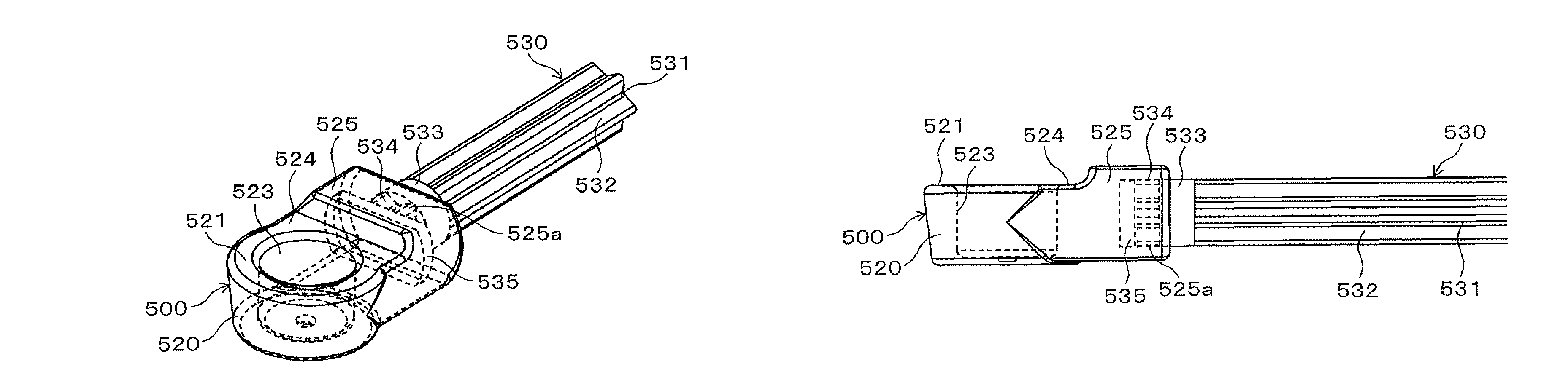
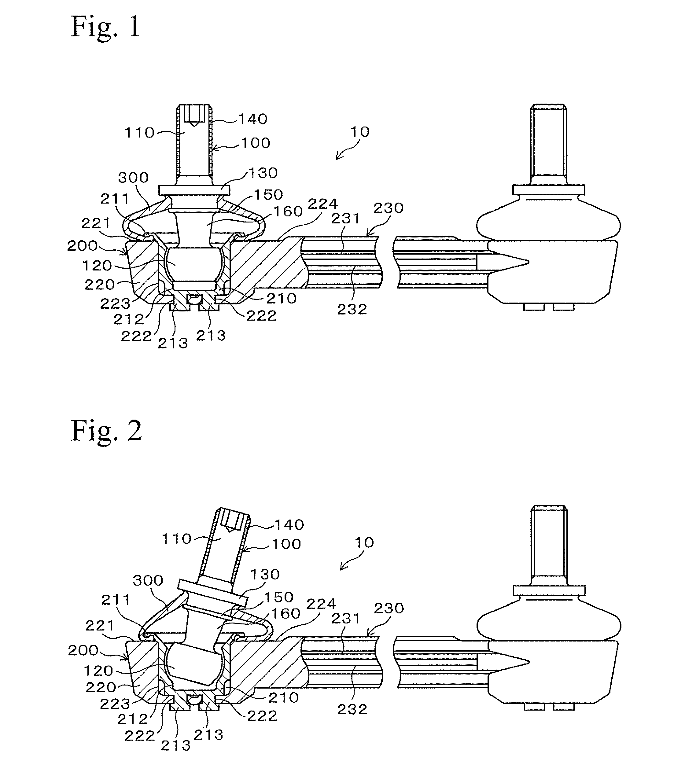
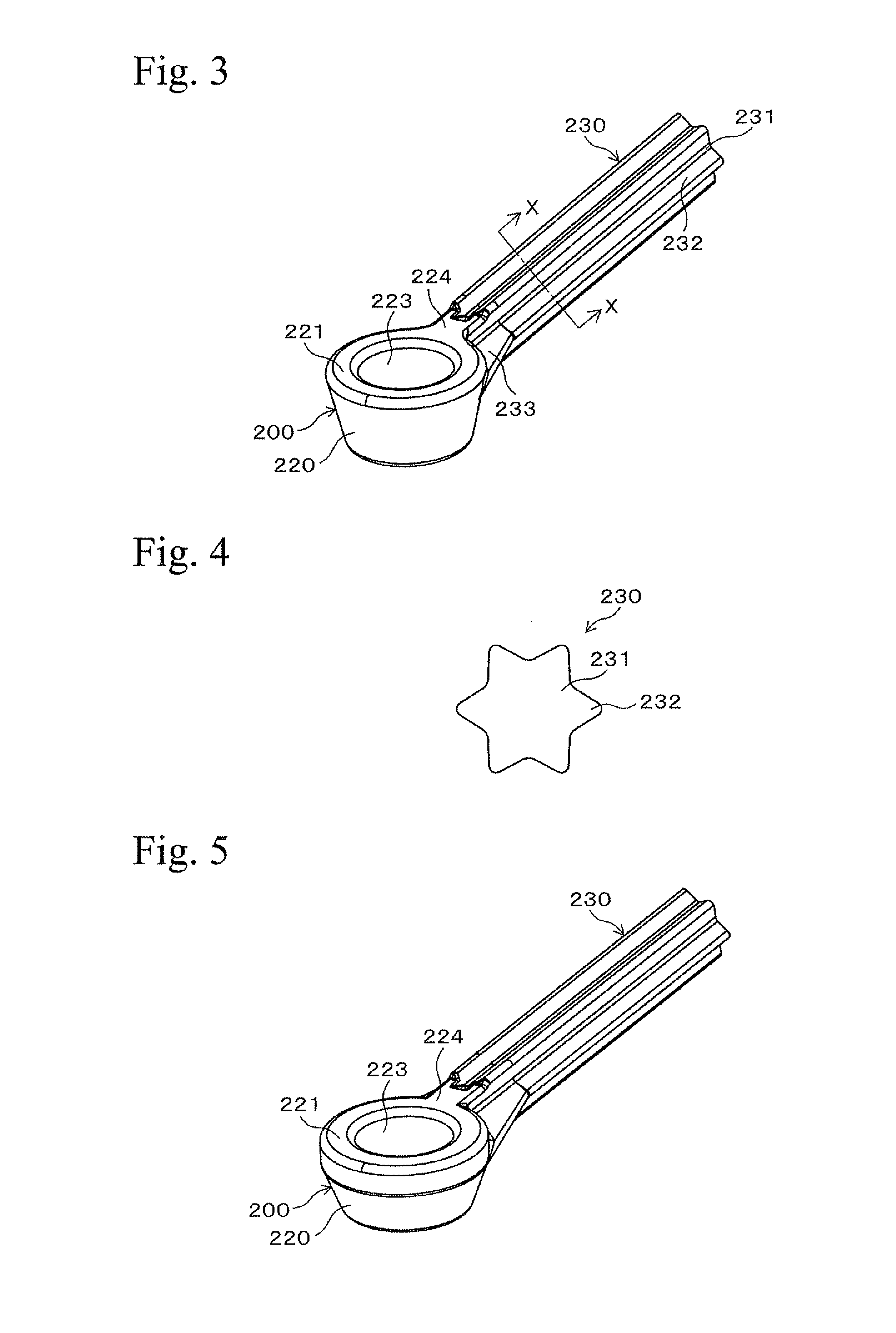
[0038]An embodiment of the present invention will be explained hereinafter. FIG. 1 is a diagram which shows a ball joint. FIG. 2 is a diagram showing a condition in which a ball joint is vibrated. FIG. 3 is a perspective view showing a portion of a pivot member. FIG. 4 is a cross sectional view which is taken along line X-X in FIG. 3 and which shows a support bar. FIG. 5 is a perspective view showing a first modification example of a pivot member. FIG. 6 is a perspective view showing a second modification example of a pivot member. FIG. 7 is a perspective view showing a third modification example of a pivot member. FIGS. 8A and 8B are cross sectional views showing a modification example of a support bar. FIG. 8A is a cross sectional view showing a first modification example of a support bar. FIG. 8B is a cross sectional view showing a second modification example of a support bar.

[0039]As shown in FIGS. 1 and 2, a ball ...

second embodiment

2. Second Embodiment

Construction of Pivot Member of Second Embodiment

[0067]A second embodiment of the ball joint of the present invention will be explained with reference to the drawings. In the second embodiment of the ball joint, the housing and the support bar of the pivot member of the first embodiment are modified. Thus, constructions of the housing and the support bar of the pivot member will be explained mainly, and explanation of the same components as those in the first embodiment will be omitted.

[0068]FIG. 10 is a diagram which shows a ball joint according to a second embodiment. FIGS. 11A and 11B are views showing a portion of a pivot member according to a second embodiment. FIG. 11A is a perspective view of the portion of the pivot member. FIG. 11B is a side view of the portion of the pivot member. FIGS. 12A and 12B are views showing a portion of a pivot member according to a second embodiment. FIG. 12A is a perspective view of the portion of the pivot member. FIG. 12B i...


PUM

PropertyMeasurementUnit
weightaaaaaaaaaa
weightaaaaaaaaaa
lengthaaaaaaaaaa

Abstract

A ball joint, which has high reliability and reduced weight, is provided. A ball joint includes: a ball stud having a columnar stud portion and a ball portion which has a spherical side surface and a center positioned on an axis of the stud portion; a ball seat which is made of a resin and has a spherical recess portion into which the ball portion is relatively rotatably and slidably fitted; a housing which is made of a resin and holds the ball seat therein; and a support bar which is integrally formed with the housing, wherein the support bar has a bar portion which is a center portion extending along an axis of the support bar.

Description

TECHNICAL FIELD[0001]The present invention relates to a ball joint provided to stabilizers of vehicles (automobiles and the like), and to a production method therefor.BACKGROUND ART[0002]For example, in a suspension mechanism of a vehicle, in order to rotatably and vibratably connect two portions (for example, a stabilizer and a shock absorber, or a stabilizer and a suspension arm) which can move relatively, a ball joint may be used.[0003]This ball joint is equipped with a ball stud, a ball seat, a housing, a support bar, and a dust cover. The ball stud has a stud portion and a ball portion. The ball seat has a bearing function and the ball portion is press-fitted therein. The housing holds the ball seat therein. The support bar supports the housing. The dust cover prevents infiltration of foreign matter which may inhibit sliding and vibration of the ball portion of the ball stud in the ball seat.[0004]In a production method for this ball joint, a housing and a support bar were sepa...

Claims


Application Information

Patent Timeline
Patent Type & Authority Patents(United States)
IPC IPC(8): F16C11/00
CPCB60G7/001F16C7/02F16C11/0657B60G7/005Y10T403/32729B60G2204/416B60G2206/011B60G2206/014B60G2206/016B60G2206/017B60G2206/11B60G2206/7104B60G2206/81012B60G2206/82092B60G2206/821B60G2206/91Y10T403/32631F16C11/0685F16C2208/36F16C2208/52F16C2208/66F16C2326/05
Inventor KURODA, SHIGERU
Owner NHK SPRING CO LTD
Why Eureka
Try Eureka