Tool holder

a tool and holder technology, applied in the field of tool holders, can solve the problems that chips or machining fluid cannot be adhered to the id tag, and achieve the effect of prolonging the life of the id tag

Active Publication Date: 2013-02-19
MAKINO MILLING MASCH CO LTD
View PDF19 Cites 32 Cited by
  • Summary
  • Abstract
  • Description
  • Claims
  • Application Information

AI Technical Summary

Benefits of technology

[0010]Thus, one object of the present invention is to provide a tool holder having a hollow taper shank, wherein a chip or machining fluid cannot become adhered to an ID tag and the ID tag is not likely to be damaged by external impact. The other object of the invention is to provided a tool holder wherein the rotational balance thereof cannot be deteriorated even when an ID tag is attached to the tool holder.
[0013]According to the present invention, a recess is formed at the central part of the bottom surface of the hollow portion, and the ID tag is positioned in the recess. Therefore, a chip or machining fluid cannot become adhered to the ID tag, and the ID tag is unlikely to be damaged by external impact, whereby life of the ID tag may be extended.

Problems solved by technology

Therefore, a chip or machining fluid cannot become adhered to the ID tag, and the ID tag is unlikely to be damaged by external impact.

Method used


Image

  • Tool holder
  • Tool holder

Examples


Embodiment Construction

[0017]Preferred embodiments of the present invention will now be described with reference to the accompanying drawings.

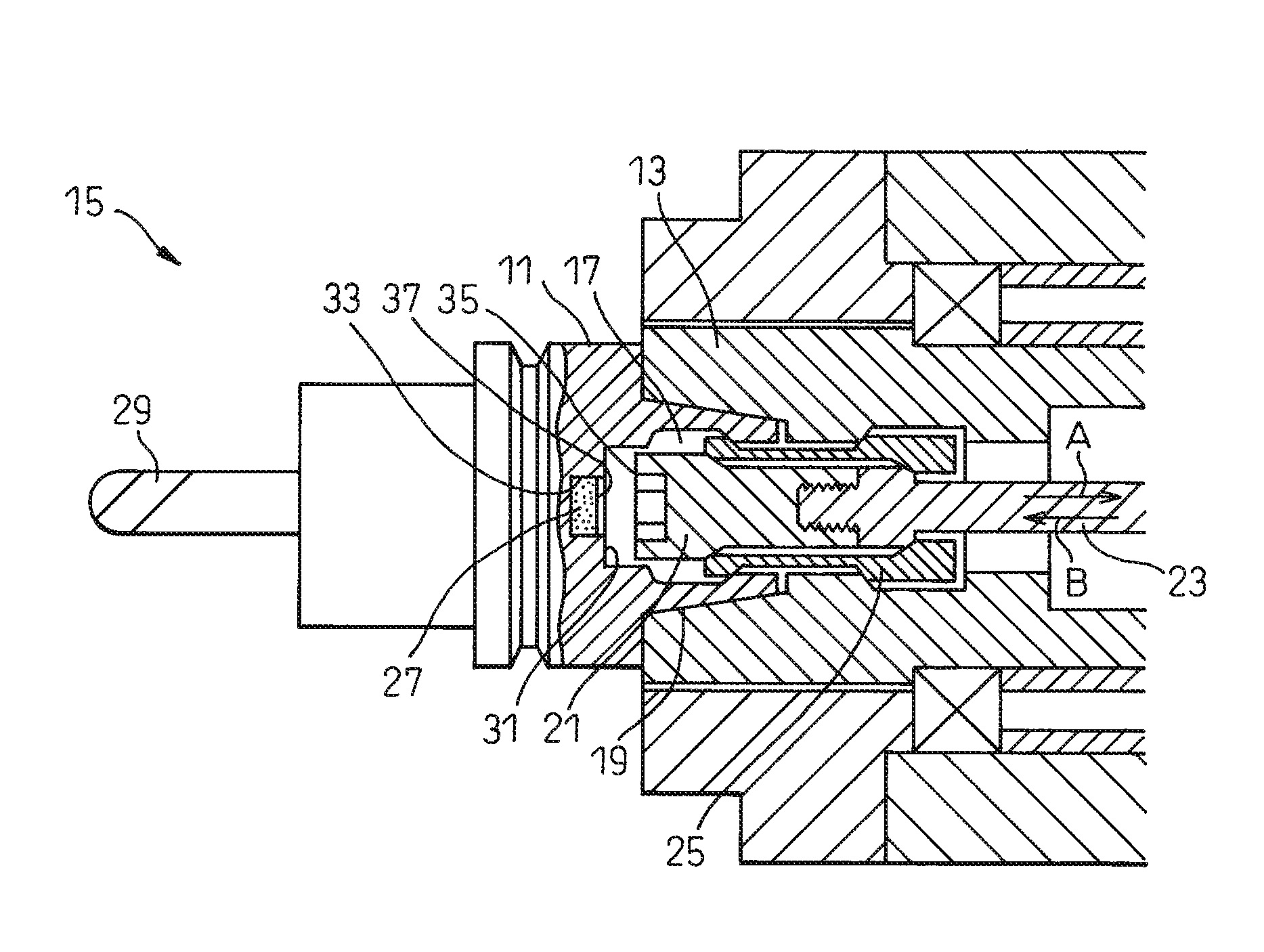
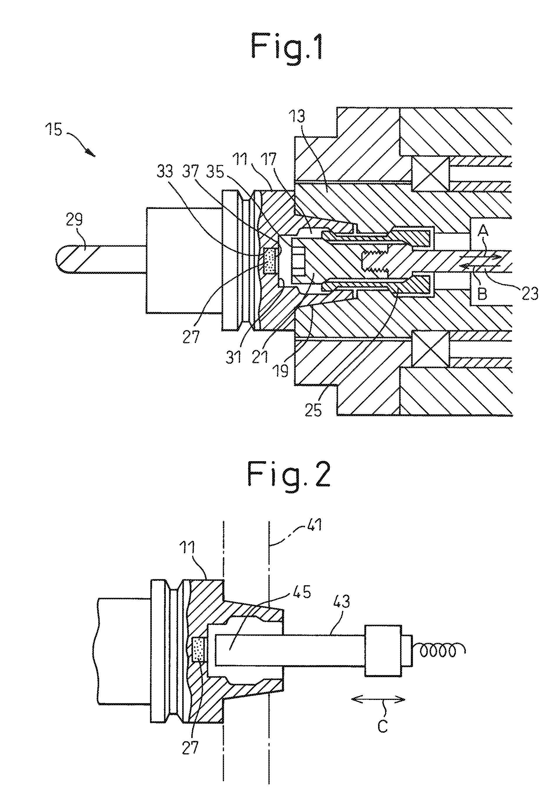
[0018]FIG. 1 shows a spindle device 15 of a machine tool, having a main spindle 13 and a tool holder 11 equipped with spindle 13. In the present invention, a side of tool holder 11, where a tool 29 is held, is referred to as a front side, and a side of tool holder 11, where a taper shank 19 is formed, is referred to as a rear end. In the embodiment, the invention is applied to a tool holder having an HSK shank. Tool holder has a taper shank 19 having a hole or hollow portion 17 which is opened in the rear direction. When tool holder 11 is attached to spindle 13, a drawbar 23, having a collet driver 21 attached to a front end thereof, is moved to the rear side of the spindle, as indicated by an arrow A. Then, a split collet 25, positioned in hole 17 of tool holder 11, is expanded so as to contact an inner surface of hole 17. Drawbar 23 is biased toward the rear side ...


PUM

PropertyMeasurementUnit
shapeaaaaaaaaaa
rotational angleaaaaaaaaaa
sizeaaaaaaaaaa

Abstract

An ID tag (27) is attached to a bottom surface (31) of a hollow portion (17) of a tool holder (11) having a hollow taper shank. Concretely, a circular recess (33) is formed on bottom surface (31) of hollow portion (17), and ID tag (27) is attached in recess (33) by means of adhesive or the like. The center of circular recess (33) coincides with a rotation axis of tool holder (11).

Description

TECHNICAL FIELD[0001]The present invention relates to a tool holder equipped with a main spindle of a machine tool, and in particular, relates to a tool holder having an ID tag, by which reading or writing information regarding the tool holder and / or a tool held by the holder is possible.BACKGROUND ART[0002]As a tool holder having a hollow taper shank equipped with a main spindle of a machine tool, a tool holder having a shank specified in Deutsche Industrie Normen (DIN) 69893 (HSK shank), and a tool holder having a shank developed by Kennametal Inc. (KM shank) are known.[0003]Various kinds of means, which identify the type or model number of a tool equipped with a spindle of a machine tool, have been proposed. For example, FIG. 2 of U.S. Pat. No. 3,704,510 discloses a tool holder having a coded collar. In this case, a binary code is read by using a switch mechanism based on a combination of a groove and a ring formed in the collar.[0004]Japanese Unexamined Patent Publication (Kokai...

Claims


Application Information

Patent Timeline
Patent Type & Authority Patents(United States)
IPC IPC(8): B23C5/26B23C9/00
CPCB23Q3/15546G05B2219/49304Y10T409/309408Y10T408/21Y10T279/21Y10T483/134Y10T408/16Y10T409/30952Y10T409/309464Y10T279/34Y02P90/02
Inventor KANEKO, HIROO
Owner MAKINO MILLING MASCH CO LTD
Why Eureka
Try Eureka