Zoom lens and imaging apparatus including focus cam for converting rotation amounts into focus lens group movement

a zoom lens and focus cam technology, applied in the field of zoom lenses and imaging apparatuses, can solve the problems of speed and accuracy of focusing at the time of zooming, the inability to accurately obtain af evaluation values, and the inability to reduce the size of the instrument, so as to achieve accurate and high-speed contrast, reduce the effect of zoom movement and simple method

Inactive Publication Date: 2013-02-19
PANASONIC CORP
View PDF28 Cites 4 Cited by
  • Summary
  • Abstract
  • Description
  • Claims
  • Application Information

AI Technical Summary

Benefits of technology

[0019]To solve the above problems, a zoom lens and an imaging apparatus are provided, that can move a focus lens in a sufficiently wide area upon contrast AF even when a zoom position is at a wide-angle end and a subject distance is infinite, and realize the contrast AF accurately.
[0021]With the above configuration, an over infinity margin area can be secured through the entire zoom area, so that accurate and high-speed contrast AF can be realized by a simple method.
[0024]Further, the lift amount of the focus cam may be defined by the cam curve so that when a subject distance is in a predetermined range, a rotational angle of the focus driving unit from the far end position to a focus position for the subject distance in the predetermined range is constant regardless of the rotational position of the zoom driving unit. This allows the driving of the focus lens group to be easily controlled.
[0028]According to the aforementioned aspect, a distance (rotation margin) on the focus cam, from a position corresponding to an infinite position (W∞) to a position corresponding to a far end position (WF end) can be sufficiently secured even when the zoom position is at the wide-angle end. Therefore, the high-magnification zoom lens and the imaging apparatus can be provided, that can perform accurate and high-speed contrast AF in a simple method over the entire zoom area.

Problems solved by technology

However an optical system, including a reflection mirror and a view finder cause a problem in view of downsizing.
When a group of four lenses with high magnification are used as the zoom lens, speed and accuracy of focusing at the time of the zooming become a problem.
In other words, with conventional zoom lenses, the AF evaluation value cannot be accurately obtained, when the contrast AF is performed with the zoom position at the wide-angle end and the infinite (∞) subject distance.
Further, when a subject distance is within a predetermined range, the focus cam driver does not operate.

Method used


Image

  • Zoom lens and imaging apparatus including focus cam for converting rotation amounts into focus lens group movement
  • Zoom lens and imaging apparatus including focus cam for converting rotation amounts into focus lens group movement
  • Zoom lens and imaging apparatus including focus cam for converting rotation amounts into focus lens group movement

Examples


Embodiment Construction

[0044]A preferred embodiment will be described below with reference to the drawings. It should be noted that like components are denoted by like symbols.

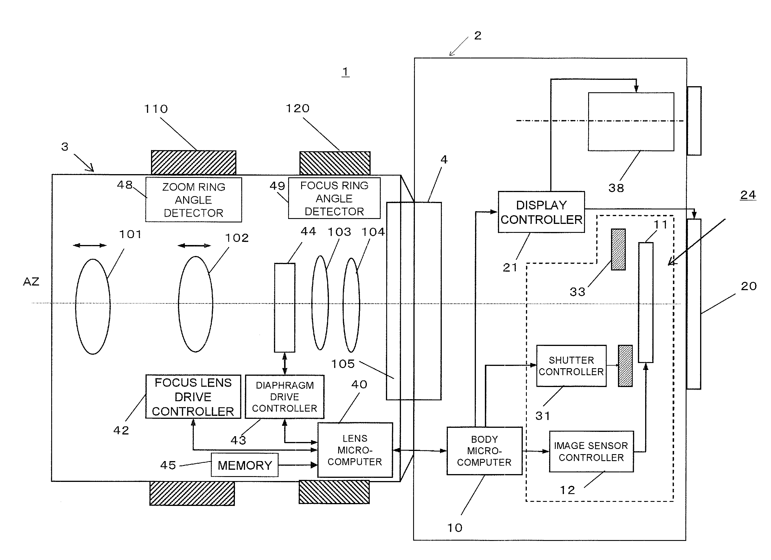
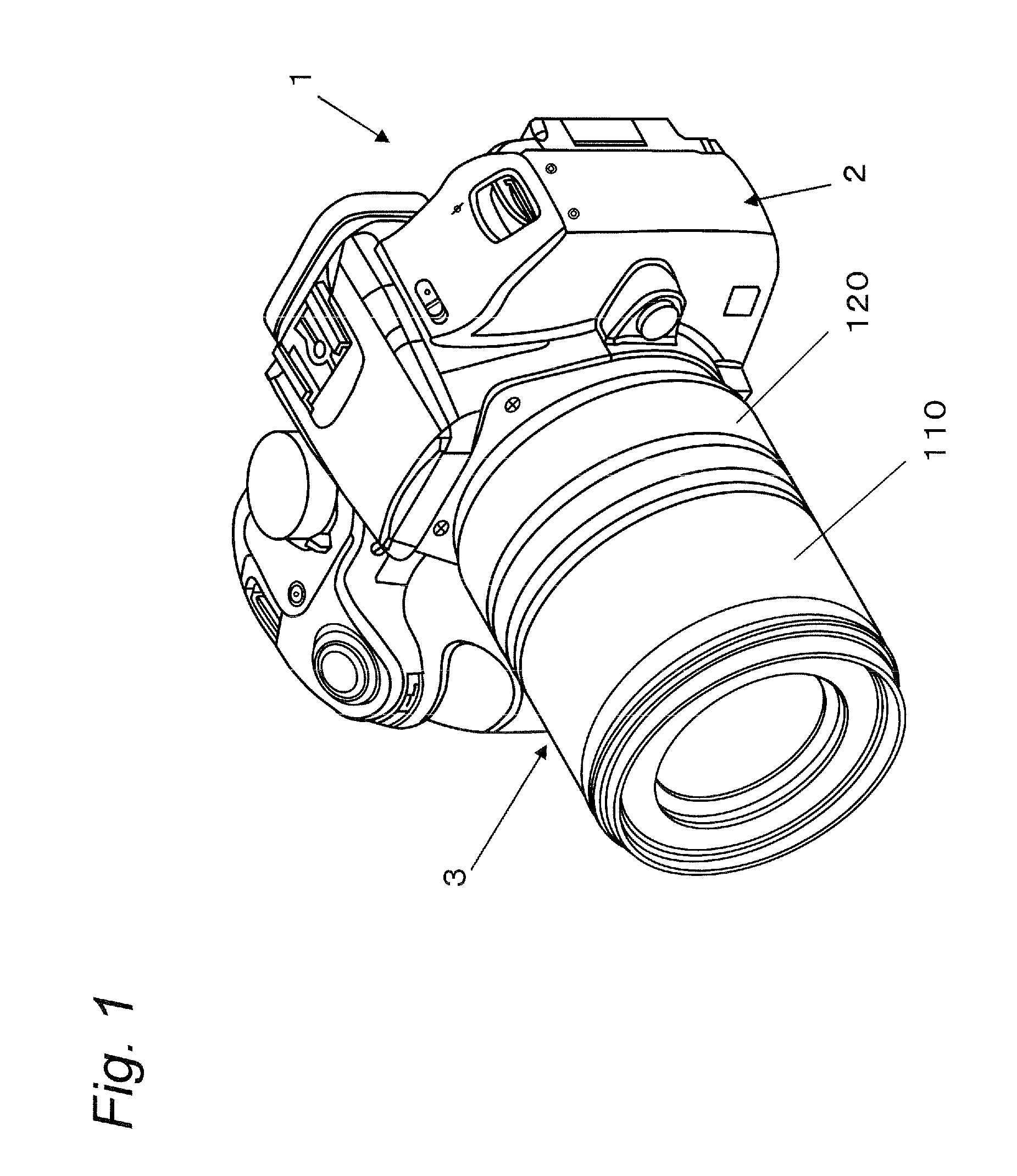
[0045]FIG. 1 is a perspective view illustrating a front side of a single-lens digital camera 1 according to an embodiment. The digital camera 1 according to the present embodiment includes a camera body 2, and an interchangeable zoom lens 3 mountable to the camera body 2 and having a zoom ring 110 and a focus ring 120.

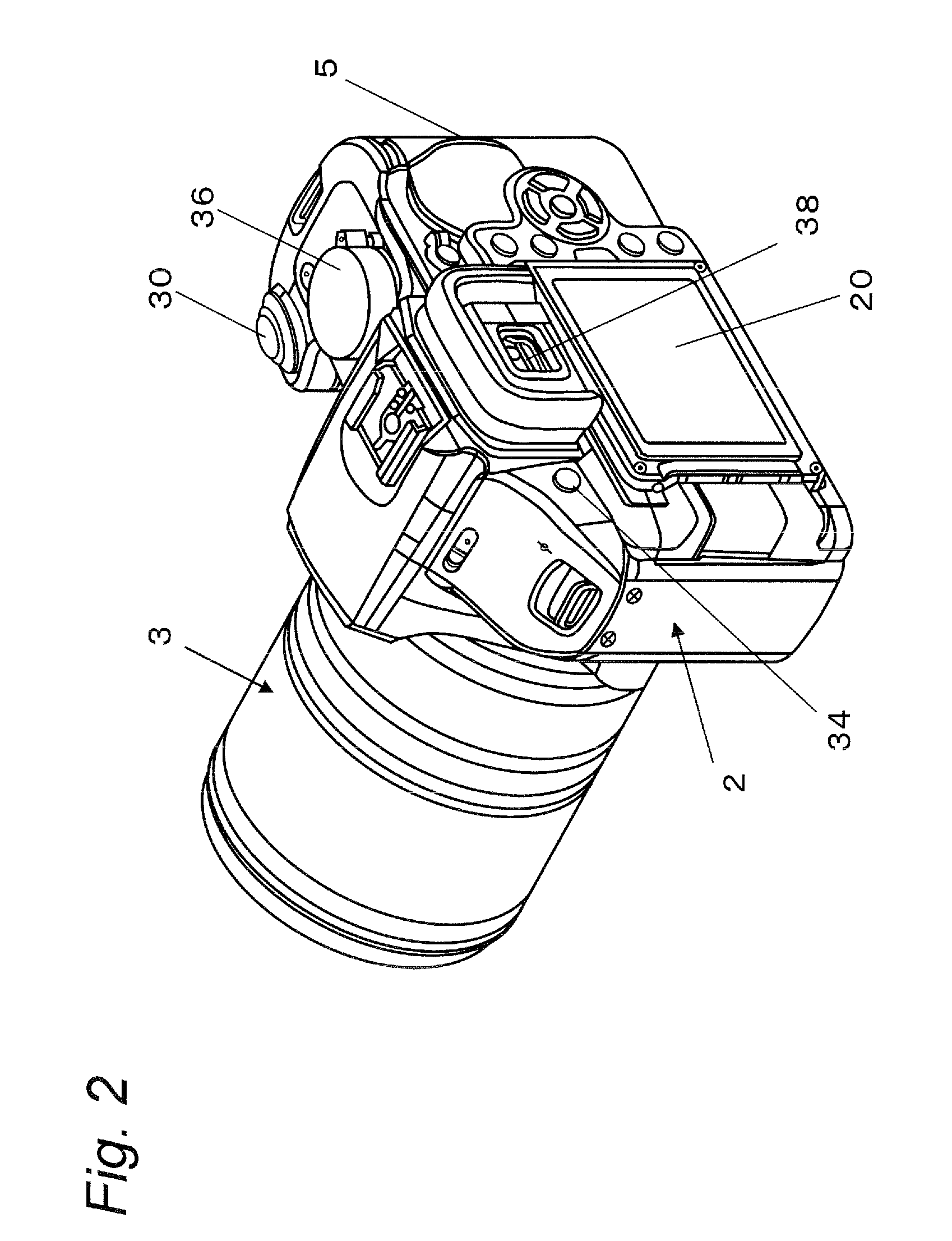
[0046]FIG. 2 is a perspective view illustrating a rear side of the digital camera 1. The rear side of the camera body 2 is provided with an electronic viewfinder 38 and a liquid crystal display monitor 20. A release button 30 and a mode switching dial 36 are provided to an upper right portion of the camera body 2, and a recording mode switching button 34 is provided to an upper left portion of the rear side of the camera body 2.

[0047]The recording mode switching button 34 is a member to be operated for switching betwee...


PUM


Abstract

A zoom lens includes a focus cam for converting a first rotation amount given upon a focus operation into a movement of the focus lens group and further converting a second rotation amount given upon a zoom operation into the movement of the focus lens group, and a focus cam follower engaged with the focus cam and operable to move in the focus cam. The focus cum follower rotates in the focus cum according to the rotation amount of the zoom driving unit to move the focus lens group. A lift amount of the focus cam is defined so that a rotation amount of the focus driving unit from a far end position to an infinite position when the rotation position of the zoom driving unit is at a wide-angle end becomes larger than the rotation amount when the rotating position of the zoom driving unit is at a telephoto end.

Description

BACKGROUND[0001]1. Technical Field[0002]The technical field relates to a zoom lens and an imaging apparatus suitable for contrast AF (Autofocus).[0003]2. Related Art[0004]In recent years, a digital single-lens reflex camera capable of converting an optical image of a subject into an electric image signal so as to record it to a recording medium such as a semiconductor memory. With such a digital single-lens reflex camera, a user can take a picture of a subject while viewing the subject through either of an optical finder and a liquid crystal display monitor provided to a rear side of the camera. When the user views the subject through the finder, light (namely, a subject image) incident on a lens is reflected by a reflection mirror arranged on an optical path after the lens so that the optical path is changed. Then the subject image is changed into an erected image through a pentaprism and is led to the optical finder, so that the user can view the subject image passing through the ...

Claims


Application Information

Patent Timeline
Patent Type & Authority Patents(United States)
IPC IPC(8): G03B13/00H04N5/232H04N5/262G02B15/14
CPCG02B7/10H04N5/23209H04N5/23212H04N5/23296H04N23/663H04N23/673H04N23/633H04N23/69
Inventor ABE, TAKASHI
Owner PANASONIC CORP
Why Eureka
Try Eureka