Electronic apparatus

a technology of electronic equipment which is applied in the direction of electrical equipment casings/cabinets/drawers, cooling/ventilation/heating modifications, instruments, etc., can solve the problems of insufficient heat dissipation, limited arrangement of cooling fan and heat dissipation fin, and difficult to make the heat dissipation structure sufficiently compact, etc., to achieve the effect of reducing rigidity, ensuring rigidity, and reducing rigidity

Active Publication Date: 2013-02-19
PANASONIC CORP
View PDF19 Cites 0 Cited by
  • Summary
  • Abstract
  • Description
  • Claims
  • Application Information

AI Technical Summary

Benefits of technology

[0011]With the foregoing in mind, it is an object of the present invention to provide an electronic apparatus with a heat dissipation structure that can maintain the liquid tightness of a heat dissipation chamber including a cooling fan with respect to the inside of a main unit case, and also can ensure the rigidity of the main unit case sufficiently.
[0014]With the above configuration, the rigidity of the main unit case can be ensured sufficiently while maintaining the liquid tightness between the inside of the main unit case and the heat dissipation chamber. Since the air channel for communicating the heat dissipation chamber with the outside of the main unit case has a structure with higher rigidity due to the plate-shaped ribs, a reduction in rigidity caused by the presence of the air channel can be avoided.

Problems solved by technology

Therefore, it is likely that the configuration of a conventional heat dissipation device cannot dissipate heat sufficiently.
Moreover, in the case of the electronic apparatus for which compactness is critical such as the notebook PC, the arrangement of the cooling fan and the heat dissipation fin is limited strictly.
However, it is difficult to make the heat dissipation structure sufficiently compact.
Moreover, a decrease in the rigidity of the case caused by providing the inlet or outlet in the side wall of the case may be a problem.

Method used


Image

  • Electronic apparatus
  • Electronic apparatus
  • Electronic apparatus

Examples


embodiment 1

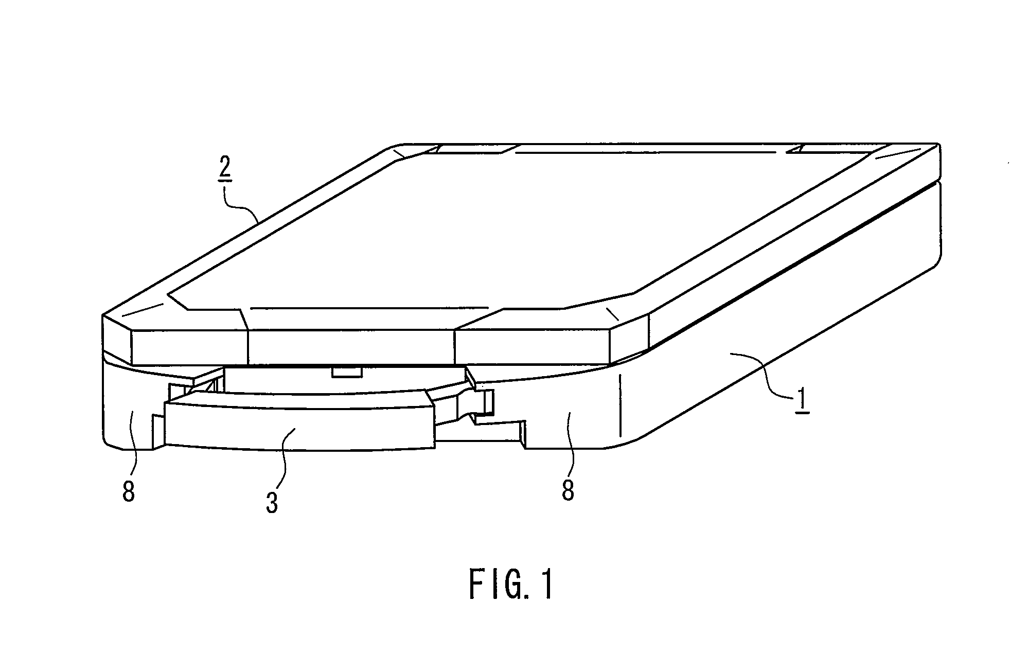
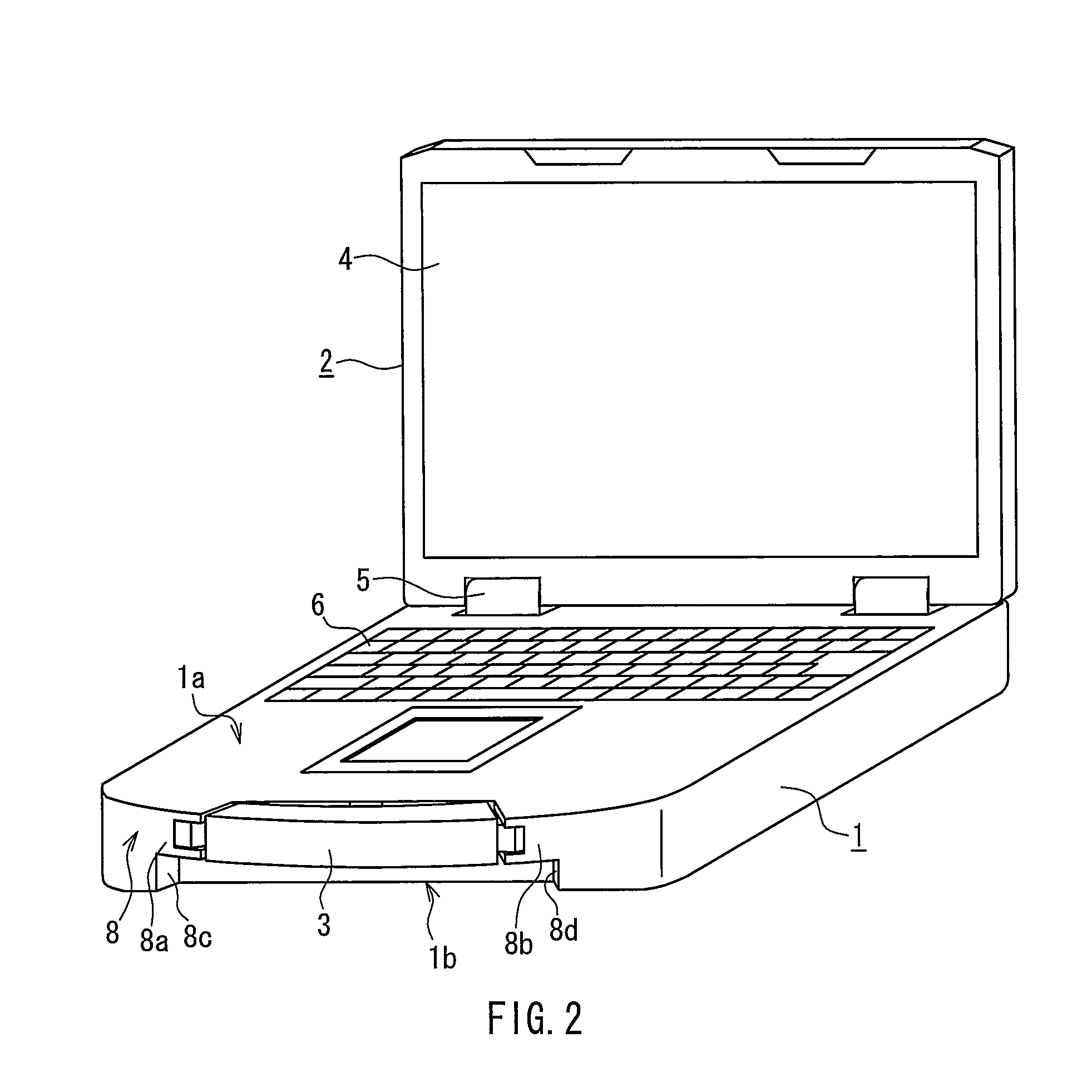
[0045]FIG. 1 is a perspective view showing the appearance of a notebook PC as an example of an electronic apparatus in Embodiment 1. The notebook PC includes a main unit case 1, a display unit case 2, and a hand grip 3. FIG. 1 shows a non-operating state. FIG. 2 is a perspective view of the notebook PC in an operating state. The upper side and the lower side of the main unit case 1 when the notebook PC is in the operating state are defined as a main unit upper surface 1a and a main unit lower surface 1b, respectively.

[0046]The main unit case 1 contains a CPU, a circuit board on which various electric elements are mounted, a hard disk drive, a battery, or the like. The display unit case 2 is provided with a liquid crystal display 4 for displaying images, characters, or the like. The display unit case 2 is supported rotatably by the main unit case 1 with hinges 5. A keyboard 6 and a pointing device 7 are provided on the main unit upper surface 1a.

[0047]The pointing device 7 is fixed ...

embodiment 2

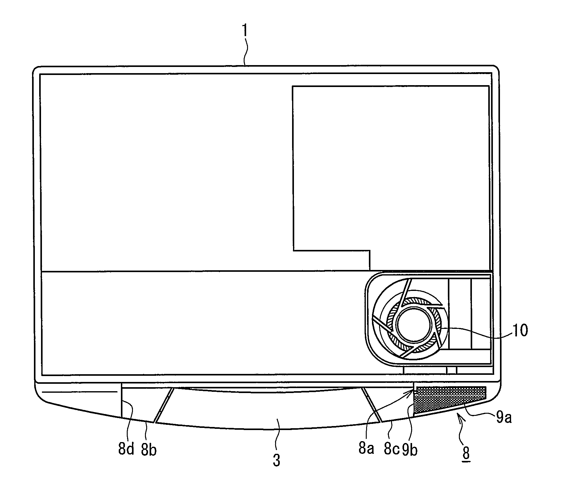
[0069]A notebook PC as an example of an electronic apparatus in Embodiment 2 will be described with reference to FIGS. 15 to 16. The notebook PC of this embodiment has the same configuration as that of the notebook PC of Embodiment 1 as shown in FIGS. 1 to 14, and therefore the following explanation also refers to some of the drawings in Embodiment 1. This embodiment is characterized in that the inlet constituting the heat dissipation structure includes the first inlet 9a and the second inlet 9b, as shown in FIGS. 3, 5, etc. In this embodiment, the first inlet 9a and the second inlet 9b are formed continuously via the edge 9c that forms the corner.

[0070]FIG. 15 is an enlarged perspective view of the grip holder 8 in the posture of the notebook PC as shown in FIG. 3. As shown in FIG. 15, the inlets through which the cooling fan 10 draws air from the outside are composed of the first inlet 9a and the second inlet 9b, so that the air intake can be performed reliably. For example, when ...


PUM


Abstract

An electronic apparatus includes the following: a heat dissipation chamber that is formed by liquid tightly separating the inside of a main unit case with a partition, has an inlet air vent and an outlet air vent in the partition, and includes a heat dissipation portion; a cooling fan that is located in the heat dissipation chamber; an inlet that is provided in the main unit case to introduce outside air into the heat dissipation chamber through the inlet air vent; and an outlet that is provided in the main unit case to exhaust an air flow sent from the cooling fan to the outside through the outlet air vent. An air channel that extends from the inlet air vent through a side wall of the main unit case to communicate the heat dissipation chamber with the inlet is liquid tightly sealed from the internal space of the main unit case with a sealing wall. A plurality of plate-shaped ribs are provided in the air channel so as to extend in a flow path direction and arranged in a lateral direction of the inlet air vent. The rigidity of the main unit case can be ensured sufficiently while maintaining the liquid tightness between the inside of the main unit case and the heat dissipation chamber.

Description

BACKGROUND OF THE INVENTION[0001]1. Field of the Invention[0002]The present invention relates to an electronic apparatus including a heat generating element, e.g., a notebook PC (personal computer) including a heat generating element such as a CPU (central processing unit). In particular, the present invention relates to a heat dissipation structure for dissipating heat from the heat generating element.[0003]2. Description of Related Art[0004]For example, in the case of a notebook PC, the amount of heat generated from a heat generating element such as a CPU increases as the performance of the notebook PC is improved. Therefore, it is likely that the configuration of a conventional heat dissipation device cannot dissipate heat sufficiently. Thus, a high-performance heat dissipation structure has been demanded. For example, when the heat dissipation structure uses an air flow produced by a cooling fan, the shape and arrangement of a heat dissipation fin, the interrelationship between ...

Claims


Application Information

Patent Timeline
Patent Type & Authority Patents(United States)
IPC IPC(8): H05K7/20
CPCG06F1/203G06F2200/201
Inventor SENOH, TOSHIYAMORI, TAKESHISATO, JUN
Owner PANASONIC CORP
Why Eureka
Try Eureka