Temperature control method, method of obtaining a temperature correction value, method of manufacturing a semiconductor device and substrate treatment apparatus
a technology of temperature correction value and temperature control method, which is applied in the direction of process and machine control, lighting and heating apparatus, instruments, etc., can solve the problems of insufficient above countermeasures, error between the temperature of the treatment substrate and the detection temperature, etc., and achieve the effect of effective us
- Summary
- Abstract
- Description
- Claims
- Application Information
AI Technical Summary
Benefits of technology
Problems solved by technology
Method used
Image
Examples
first embodiment
(First Embodiment)
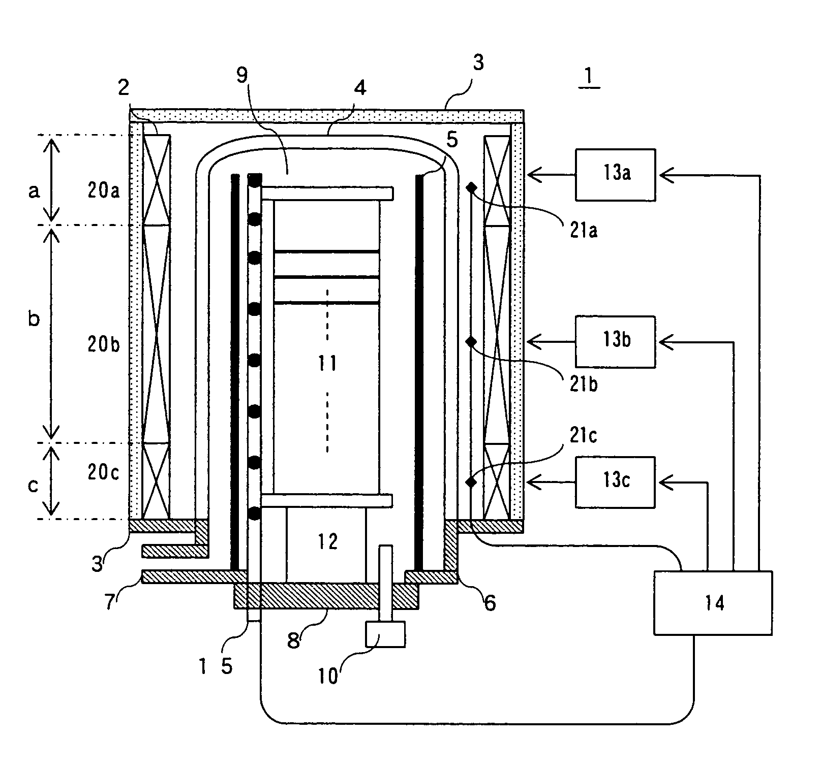
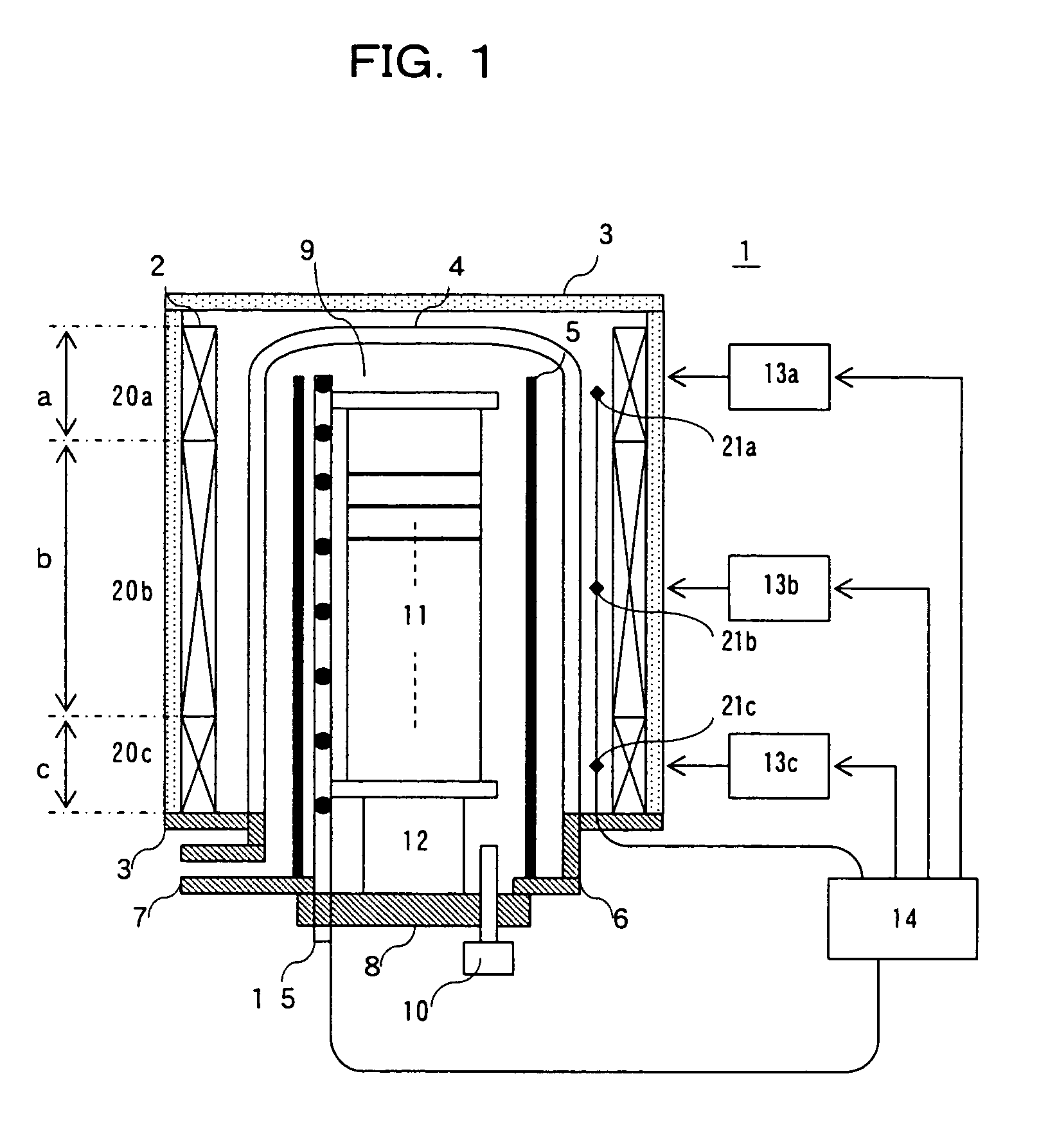
[0057]In a first embodiment, a virtual temperature based on detection temperatures of profile temperature sensors 15 shown in FIG. 1 is controlled to be coincident with a target temperature. The virtual temperature in the first embodiment is determined in connection with each of plural in-furnace temperature sensors 21. Proper detection temperatures are selected from detection temperatures of many profile temperature sensors 15 and averaged to obtain the average temperature as the virtual temperature. The in-furnace temperature sensor 21 is provided every zone, and thus the virtual temperature may be determined in connection with each zone.
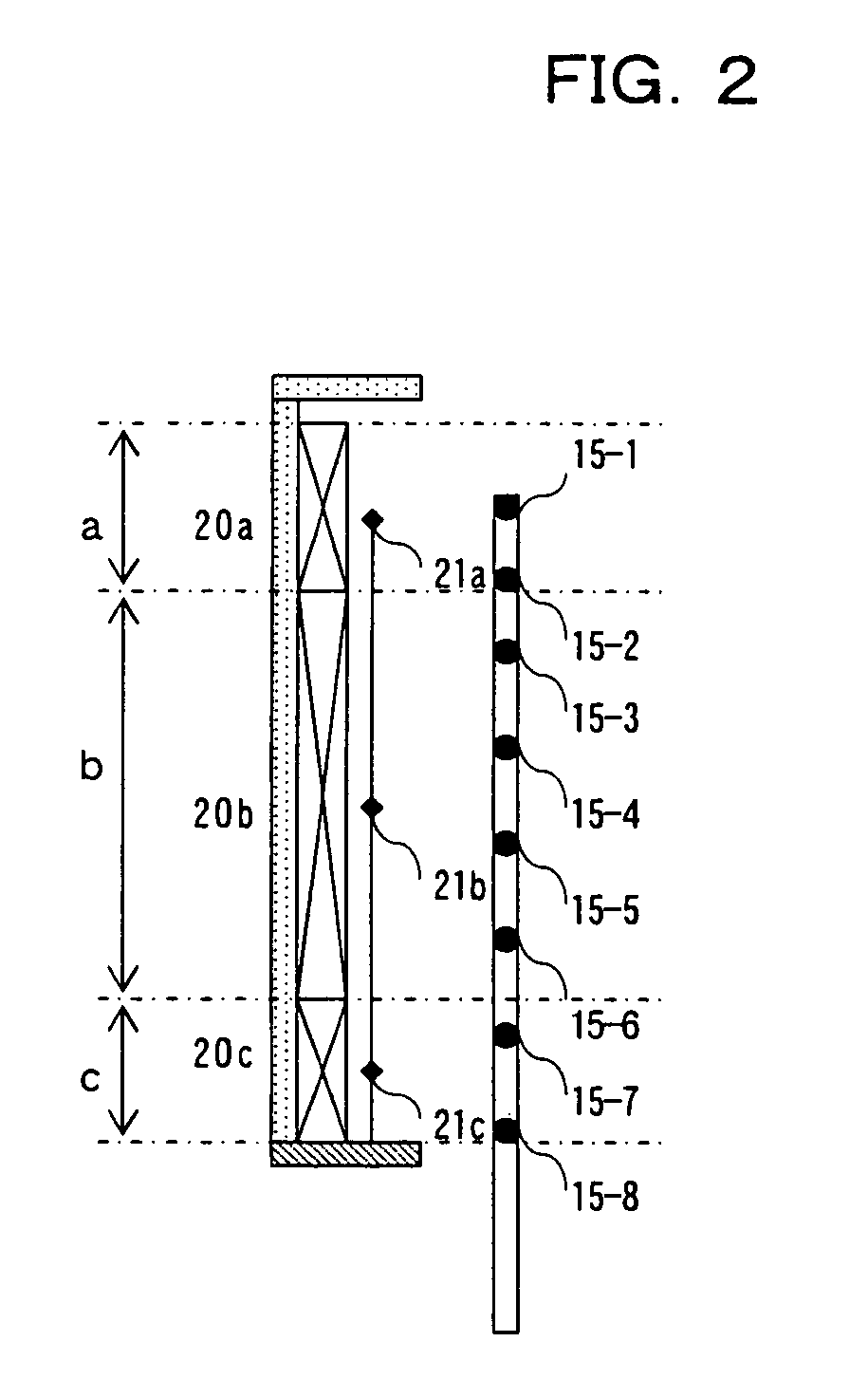
[0058]The virtual temperature will be described in more detail with reference to FIG. 2.
[0059]For example, the virtual temperatures are set as follows. With respect to the in-furnace temperature sensor 21a, an average temperature of profile temperatures sensors 15-1 and 15-2 contained in the a zone area corresponding to the in-fu...
second embodiment
(Second Embodiment)
[0067]In the first embodiment, the detection temperature of the profile temperature sensor 15 contained in each zone area is set to the virtual temperature corresponding to each in-furnace temperature sensor 21. However, it may be modified so that some profile temperature sensors 15 located in a range which affects each in-furnace temperature sensor 21 are selected and the average temperature of the detection temperatures of the selected profile temperature sensors 15 is set as the virtual temperature.
[0068]For example, the virtual temperature corresponding to the in-furnace temperature sensor 21a may be set to the average temperature of the detection temperatures of the profile temperature sensors 15-1 to 15-4 which are expected to be affected by the heater 20a, the virtual temperature corresponding to the in-furnace temperature sensor 21b may be set to the average temperature of the detection temperatures of the profile temperature sensors 15-2 to 15-7 which are...
third embodiment
(Third Embodiment)
[0070]With respect to the virtual temperature in the third embodiment, the virtual temperature is determined in connection with each of plural in-furnace temperature sensors 21, and each value of detection temperatures of the profile temperature sensors 15 is multiplied by a predetermined weighting factor corresponding to each detection temperature (for example, the weighting factors of the profile temperature sensors 15-1, 15-2 located in the neighborhood of the in-furnace temperature sensor 21a are set to large numerical values, and the numerical value allocated to the weighting factor is reduced as the profile temperature sensor is far away from the in-furnace temperature sensor 21a as in the case of the profile temperature sensors 15-7, 15-8, etc.), and the sum of the integration values of the detection temperatures and the weighting factors is set as the virtual temperature.
[0071]The virtual temperature of the third embodiment will be described in more detail....
PUM
| Property | Measurement | Unit |
|---|---|---|
| temperatures | aaaaa | aaaaa |
| temperature | aaaaa | aaaaa |
| thermal interference matrix | aaaaa | aaaaa |
Abstract
Description
Claims
Application Information
 - R&D
- Intellectual Property
- Life Sciences
- Materials
- Tech Scout
- Unparalleled Data Quality
- Higher Quality Content
- 60% Fewer Hallucinations
Browse by: Latest US Patents, China's latest patents, Technical Efficacy Thesaurus, Application Domain, Technology Topic, Popular Technical Reports.
© 2025 PatSnap. All rights reserved.Legal|Privacy policy|Modern Slavery Act Transparency Statement|Sitemap|About US| Contact US: help@patsnap.com


