Heat-storage-type two-position three-control separated temperature control method

A temperature control method and heat storage technology, applied in the direction of furnace control devices, waste heat treatment, lighting and heating equipment, etc., can solve the problems of heating quality influence, increase of production cost, increase of oxidation burning loss, etc., to improve the scope of application, Improve pass rate and save energy

Inactive Publication Date: 2020-03-13
HUATIAN ENG & TECH CORP MCC
View PDF5 Cites 0 Cited by
  • Summary
  • Abstract
  • Description
  • Claims
  • Application Information

AI Technical Summary

Problems solved by technology

[0005] If there is a temperature difference between the two sides of the furnace, the low temperature side must be above the discharge temperature before the discharge temperature can be qualified, which will inevitably cause the temperature on the high temperature side to exceed the discharge temperature, resulting in waste of energy, and at the same time, the oxidation burning loss will also increase relatively
[0006] 2. The temperature difference of the heating workpiece cannot be eliminated
[0007] For some heating workpieces, there is a requirement for the temperature difference. If there is a temperature difference between the two sides of the furnace, if the temperature difference is within the required range of the heating workpiece, it is acceptable. If the temperature difference is outside the required range of the heating workpiece, the heating quality will inevitably be affected. , even lead to waste products, directly increase the production cost, and also cause the instability of the quality of the heated workpiece

Method used


Image

  • Heat-storage-type two-position three-control separated temperature control method

Examples


Embodiment Construction

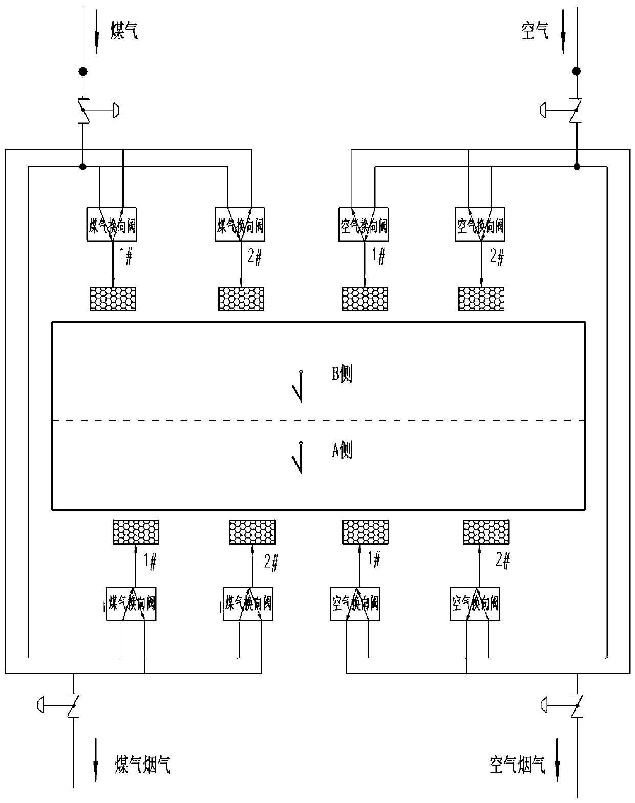
[0022] The present invention will be further described below in conjunction with the accompanying drawings.

[0023] 1. Divide a control area into two virtual temperature control areas A and B

[0024] From the point of view of the dual regenerative combustion system, a control area has only one set of air flow control valve, gas flow control valve, air smoke flow control valve, and soot flow control valve. Theoretically, the temperature of this area depends on the air flow and gas flow The control valve is used to control the furnace pressure, and the furnace pressure is controlled by the air smoke and soot flow control valve. However, it is not feasible to use the traditional control method to control the temperature of the two virtual temperature zones A and B in a control zone. New regenerative two-position three-control split-side temperature control method.

[0025] 2. Group the regenerative combustion devices in the two virtual temperature control areas of A and B into...


PUM


Abstract

The invention discloses a heat-storage-type two-position three-control separated temperature control method, and mainly aims at a problem that temperature distribution of a regenerative combustion system along a furnace width direction is not controllable. The method comprises the following steps: taking two pairs of continuous burners as a virtual heating area; taking the two burners at a same side of the furnace body along the furnace length direction in the virtual heating area as a ''combustion-smoke exhaust'' unit; and controlling each ''combustion-smoke exhaust'' unit to work in different directions periodically according to a preset program. According to the invention, a control area is divided into a left virtual temperature control area and a right virtual temperature control area; change of three control time of the two virtual temperature control areas is realized through three control states of two valve positions of a combustion reversing device, so that temperatures of the two virtual temperature control areas are changed. Through calculation of temperature change trends of the two virtual temperature control areas and simultaneous calculation and adjustment of numerical values of the three control time of combustion devices of the two virtual temperature control areas, the purpose of automatically controlling temperature distribution along the furnace width direction is achieved.

Description

technical field [0001] The invention relates to a thermal storage type two-two-three-control split-side temperature control method. Background technique [0002] The control method of the regenerative combustion system has always been a major bottleneck in the application of regenerative combustion technology. The regenerative combustion system has a characteristic in terms of method and equipment design. Because a set of control valves are used to control the burners on both sides of the furnace, Due to the characteristics of the regenerative combustion principle, it is easy to cause a deviation in the temperature on both sides of the furnace, and once the temperature difference is formed, it cannot be adjusted by physical means. [0003] And this temperature difference will have the following effects on production: [0004] 1. The discharge temperature is too high [0005] If there is a temperature difference between the two sides of the furnace, the low temperature side...

Claims


Application Information

Patent Timeline
Patent Type & Authority Applications(China)
IPC IPC(8): F27D17/00F27D21/00F27D19/00
CPCF27D17/001F27D17/004F27D19/00F27D21/0014F27D2017/007F27D2019/0018F27D2019/0028
Inventor 周炜
Owner HUATIAN ENG & TECH CORP MCC
Why Eureka
Try Eureka