
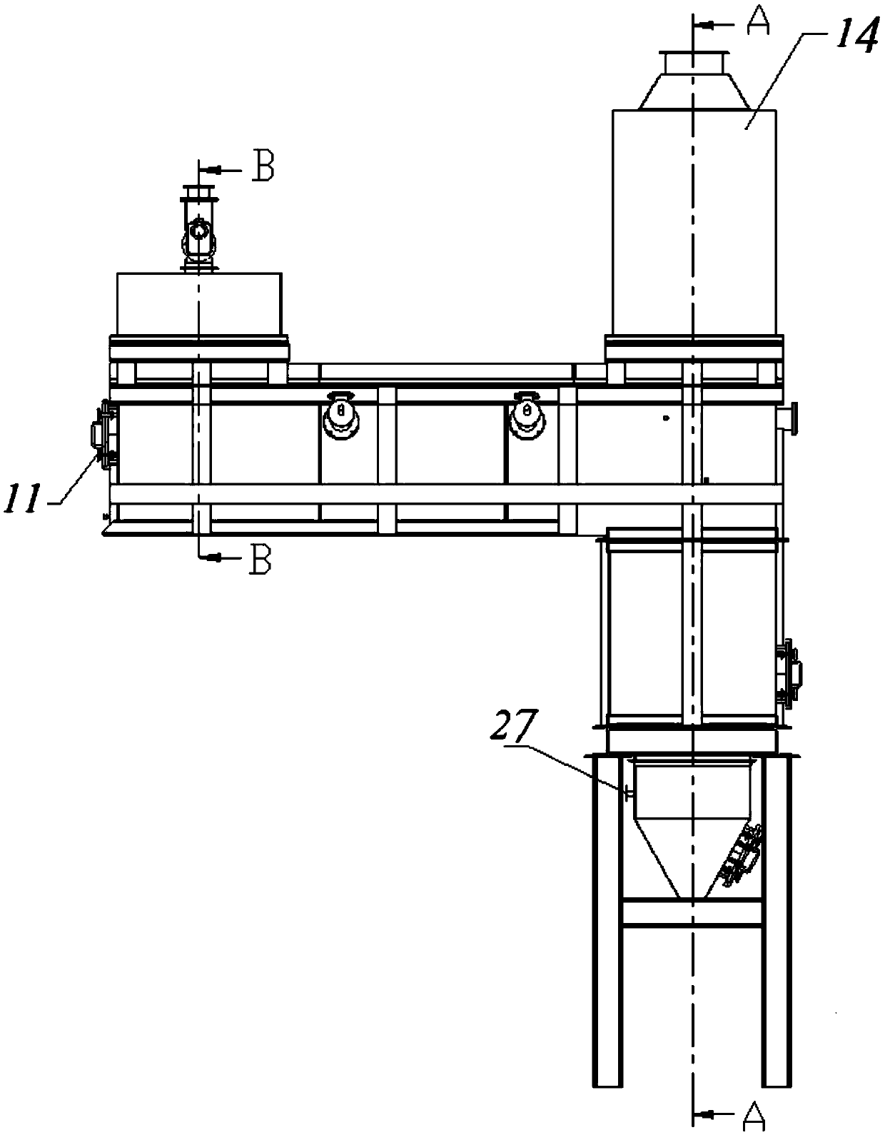
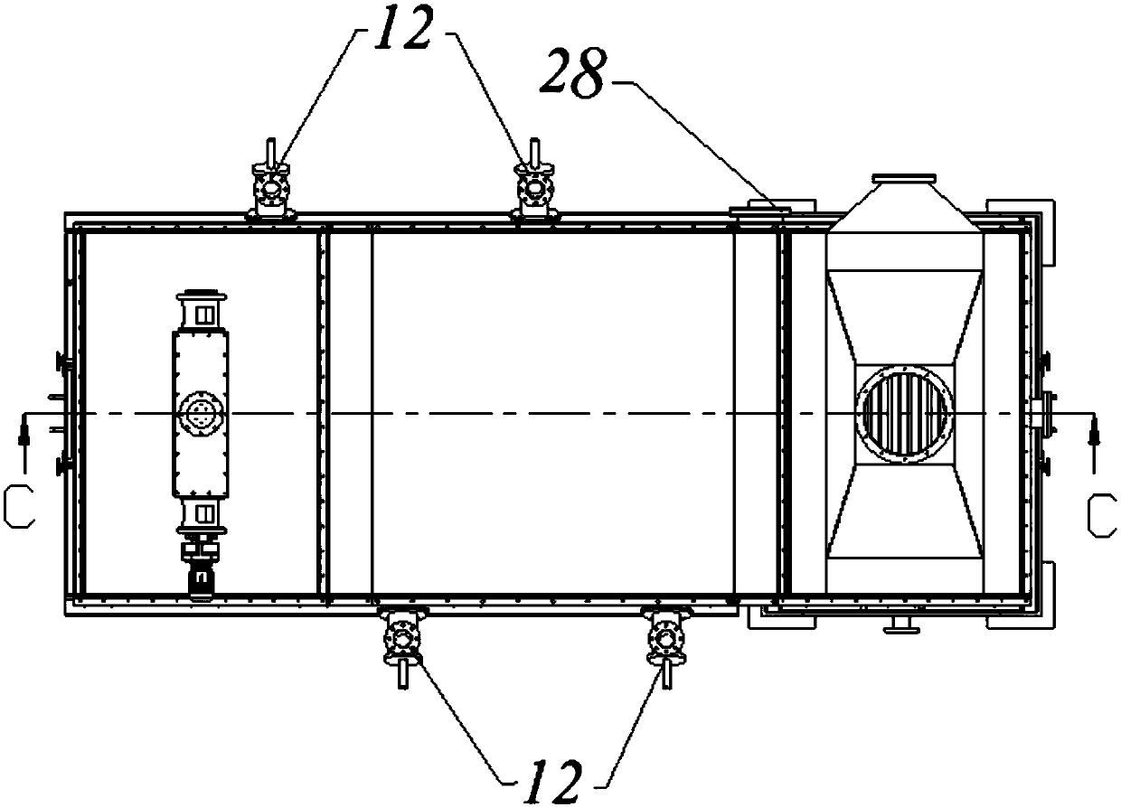
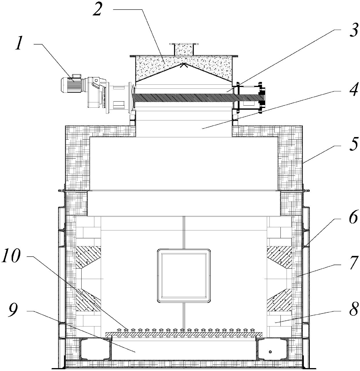
Method for recycling waste foundry sand through compound roasting device

A technology of foundry waste sand and equipment pairing, which is applied in the direction of casting molding equipment, metal processing equipment, lighting and heating equipment, etc. It can solve the problems of high heat loss, poor environmental protection effect, insufficient combustion of foundry waste sand and exhaust gas, etc. To achieve the effect of improving the demoulding rate

Active Publication Date: 2019-04-19
广西兰科资源再生利用有限公司
View PDF6 Cites 1 Cited by
  • Summary
  • Abstract
  • Description
  • Claims
  • Application Information

AI Technical Summary

Problems solved by technology

The existing thermal regeneration method is insufficient for the combustion of foundry waste sand and waste gas, resulting in a large amount of waste gas emissions, poor environmental protection effect, and relatively high heat loss
The main reason is that the feeding method of the vertical roasting furnace is from top to bottom, and the combustion chamber is at the bottom. During the feeding process, the casting waste sand is heated, but the temperature of combustion cannot be reached, and the organic matter sticking to the casting waste sand is volatilized and discharged. , and the exhaust gas is directly discharged outside without heat exchange, resulting in large heat loss, high sand production temperature, and high energy consumption

Method used


Image

  • Method for recycling waste foundry sand through compound roasting device
  • Method for recycling waste foundry sand through compound roasting device
  • Method for recycling waste foundry sand through compound roasting device

Examples


Embodiment 1

[0038]A method for recycling foundry waste sand based on compound roasting equipment, comprising the following steps:

[0039] S1. The material enters the receiving trough through the equalizing plate (not shown in the drawings), then enters the feeding protection device through the impeller and then enters the combustion chamber of the horizontal combustion chamber;

[0040] S2. The material is blown and boiled by the hot air at the bottom of the combustion chamber, and flows from the combustion chamber to the air separation and miscellaneous removal chamber. During this period, the three-stage roasting is carried out sequentially through the combustion gun. The temperature of the first-stage roasting is 300°C, and the time is 10s; The temperature is 600°C, and the time is 240s; the temperature of the three-stage roasting is 850°C, and the time is 10s;

[0041] S3. After the material is roasted, it falls into the air preheating chamber from the air separation and miscellaneou...

Embodiment 2

[0049] A method for recycling foundry waste sand based on compound roasting equipment, comprising the following steps:

[0050] S1. The material enters the receiving trough through the equalizing plate (not shown in the drawings), then enters the feeding protection device through the impeller and then enters the combustion chamber of the horizontal combustion chamber;

[0051] S2. The material is blown and boiled by the hot air at the bottom of the combustion chamber, and flows from the combustion chamber to the air separation and miscellaneous removal chamber. During this period, the three-stage roasting is carried out sequentially through the combustion gun. The temperature of the first-stage roasting is 400°C, and the time is 20s; The temperature is 800°C, and the time is 180s; the temperature of the three-stage roasting is 900°C, and the time is 20s;

[0052] S3. After the material is roasted, it falls into the air preheating chamber from the air separation and miscellaneo...

Embodiment 3

[0059] A method for recycling foundry waste sand based on compound roasting equipment, characterized in that it comprises the following steps:

[0060] S1. The material enters the receiving trough through the equalizing plate (not shown in the drawings), then enters the feeding protection device through the impeller and then enters the combustion chamber of the horizontal combustion chamber;

[0061] S2. The material is blown and boiled by the hot air at the bottom of the combustion chamber, and flows from the combustion chamber to the air separation and miscellaneous removal chamber. During this period, the three-stage roasting is carried out sequentially through the combustion gun. The temperature of the first-stage roasting is 400 ° C, and the time is 15s; The temperature is 700°C, and the time is 240s; the temperature of the three-stage roasting is 850°C, and the time is 10s;

[0062] S3. After the material is roasted, it falls into the air preheating chamber from the air ...


PUM


Abstract

The invention discloses a method for recycling waste foundry sand through a compound roasting device. The method for recycling the waste foundry sand through the compound roasting device comprises thefollowing steps that S1, materials enter a receiving tank through a material uniformizing plate, then enter a feeding protection device through an impeller and finally enter a horizontal combustion chamber; S2, the materials are blown and boiled through hot air from the bottom of the combustion chamber to flow from one end of the combustion chamber to the other end of the combustion chamber, andthree-stage roasting is conducted in the flowing process of the materials, wherein the temperature for the first stage of roasting is 300-400 DEG C, and the time for the first stage of roasting is 10-20 s; the temperature for the second stage of roasting is 600-800 DEG C, and the time for the second stage of roasting is 180-240 s; and the temperature for the third stage of roasting is 850-900 DEGC, and the time for the third stage of roasting is 10-20s; and S3, the roasted materials enter an air preheating chamber, exchange heat with cold air to be cooled to 200-300 DEG C and then are discharged, and high-temperature waste gas is exhausted after heat exchange. According to the method for recycling the waste foundry sand through the compound roasting device, the discharge temperature is lower than 300 DEG C, and the furnace temperature can be increased rapidly and can be increased to the material roasting temperature within 30 min; and the exhausted waste gas has a low temperature andcontains few hazardous substances.

Description

technical field [0001] The invention belongs to the technical field of material roasting, and in particular relates to a method for recycling foundry waste sand based on compound roasting equipment. Background technique [0002] About 90% of the castings in the foundry industry are produced by sand casting. The basic raw materials for making sand molds are foundry sand and sand binders. The commonly used sand binders can be divided into organic types (such as: phenolic resin, cold box resin, etc.) and inorganic types (such as: clay, water glass, etc.) ), and the commonly used foundry sand is silica sand (20-140 mesh particles), generally producing 1 ton of castings will produce 1-1.5 tons of foundry waste sand, a large amount of silica sand comes from nature, the scale development of the foundry industry will inevitably lead to natural silica sand resources A large number of mining and discarding of a large amount of waste sand containing harmful substances. For the sustai...

Claims


Application Information

Patent Timeline
Patent Type & Authority Applications(China)
IPC IPC(8): F27B15/00F27B15/02F27B15/08F27B15/10F27B15/14F27B15/16F27D17/00B22C5/00
CPCB22C5/00F27B15/00F27B15/02F27B15/08F27B15/10F27B15/14F27B15/16F27D17/004
Inventor 梁炎戴伟平罗桂猛刘临琦余兵
Owner 广西兰科资源再生利用有限公司
Learn More