Electric vehicle

a technology of electric vehicles and electric brakes, applied in the direction of electric devices, motor/generator/converter stoppers, dynamo-electric converter control, etc., can solve the problems of significant downhill during non-operation, vehicle slipping downhill during non-operation, and uncomfortable feeling for the crew, so as to reduce the supply of electricity and prevent the slipping of the vehicle on the slope. , the effect of reducing the discomfort of the driver

Active Publication Date: 2013-02-26
KANZAKI KOKYUKOKI MFG
View PDF19 Cites 15 Cited by
  • Summary
  • Abstract
  • Description
  • Claims
  • Application Information

AI Technical Summary

Benefits of technology

[0014]An advantage of the present invention is that and uncomfortable feeling for a driver with regard to the behavior of the vehicle when supply of electricity is stopped is reduced in a structure, in a electric vehicle, in which the drive wheel is driven with a traction electric motor.
[0015]According to a first aspect of the present invention, there is provided a electric vehicle comprising a drive wheel which is driven by a traction electric motor, a brake command device which can be operated by a driver, a brake releasing unit which is driven by supply of electricity, a brake shaft which can be rotated in two directions, wherein the brake shaft is rotatable in a brake realizing direction which is one of the two directions by an operation of the brake command device, and rotatable in a brake releasing direction which is the other one of the two directions by driving of the brake releasing unit, a friction plate which is operatively connected to the traction electric motor and which is frictionally braked when the brake shaft is rotated in the brake realizing direction, and a braking spring which applies an elastic force to the brake shaft in a direction to rotate the brake shaft in the brake realizing direction, wherein the brake releasing unit comprises a brake releasing motor which is driven by supply of electricity, a displacement member which is displaced by driving of the brake releasing motor, and a displacement permitting spring provided between the displacement member and the brake shaft, and which permits an elastic relative displacement between the displacement member and the brake shaft and applies an elastic force to the brake shaft in a direction to maintain a relative position between the brake shaft and the displacement permitting spring or the displacement member, and the brake releasing motor rotates the brake shaft against the elastic force of the braking spring in the brake releasing direction through the displacement member and the displacement permitting spring.
[0016]According to the electric vehicle of the present invention, in a structure in which the drive wheel is driven by a traction electric motor, the uncomfortable feeling for the driver with regard to the behavior of the vehicle when supply of electricity is stopped can be reduced. Specifically, when the supply of electricity to the traction electric motor is stopped, the brake shaft is rotated in the brake realizing direction by the braking spring and the drive wheel is braked. In addition, during the normal running, because the brake can be released by the driving of the brake releasing motor, there is no problem with regard to running. Moreover, when a brake command device such as a brake pedal is operated, the vehicle can be normally braked. Because of this, with the above-described stopping of the supply of electricity, the braking force is generated during the running of the vehicle, and when the vehicle is parked on a slope, even when the brake command device and the parking brake command device are not operated, the downhill slipping of the vehicle on the slope can be prevented. Because of this, the behavior of the vehicle becomes similar to that of the vehicle in which the wheel is driven by driving of the hydraulic motor. Therefore, the uncomfortable feeling for the driver can be reduced.
[0017]According to another aspect of the present invention, it is preferable that the electric vehicle further comprises a protection unit which protects the brake releasing motor.
[0018]According to the above-described configuration, endurance of the brake releasing motor can be improved and the reliability can be improved.
[0019]According to another aspect of the present invention, it is preferable that, in the electric vehicle, the protection unit comprises an actuator which is provided in the brake releasing unit, which is driven by supply of electricity in a state where the brake shaft is rotated by a predetermined angle which is set in advance in the brake releasing direction, to disable the displacement of the displacement member, and which, with stopping of the supply of electricity, enables the displacement of the displacement member and permits rotation of the brake shaft in the brake realizing direction by the braking spring.

Problems solved by technology

However, a simple replacement of the hydraulic motor with the electric motor would result in a behavior of the vehicle different from that in the case of the hydraulic motor driven vehicle when supply of electricity to the electric motor is stopped, and consequently, an uncomfortable feeling for the crew.
However, the vehicle slipping significantly downhill during non-operation of the brake pedal or side brake is not preferred because an uncomfortable feeling may be caused for the driver.
In addition, when the power supply switch is switched OFF in a state where the vehicle is parked on a slope, because the supply of electricity to the electric motor is stopped, there is a possibility that the vehicle will slip downhill during the non-operation of the brake pedal or the side brake.
Thus, there is a possibility that simple replacement of the hydraulic motor with the electric motor may cause an uncomfortable feeling for the driver with regard to the behavior of the vehicle.
On the other hand, when the motor is normally rotated and the arm is rotated in the counterclockwise direction, the pipe for automatic operation is rotated in the clockwise direction against the biasing force of the biasing spring and the pipe for manual operation is rotated in the clockwise direction, resulting in releasing of the braking of the front and rear wheels.
Such a reference does not disclose a structure for reducing the uncomfortable feeling for the driver with regard to the behavior of the vehicle when supply of electricity is stopped in a electric vehicle in which the drive wheel is driven with the traction electric motor.

Method used


Image

  • Electric vehicle
  • Electric vehicle
  • Electric vehicle

Examples


first embodiment

[First Embodiment]

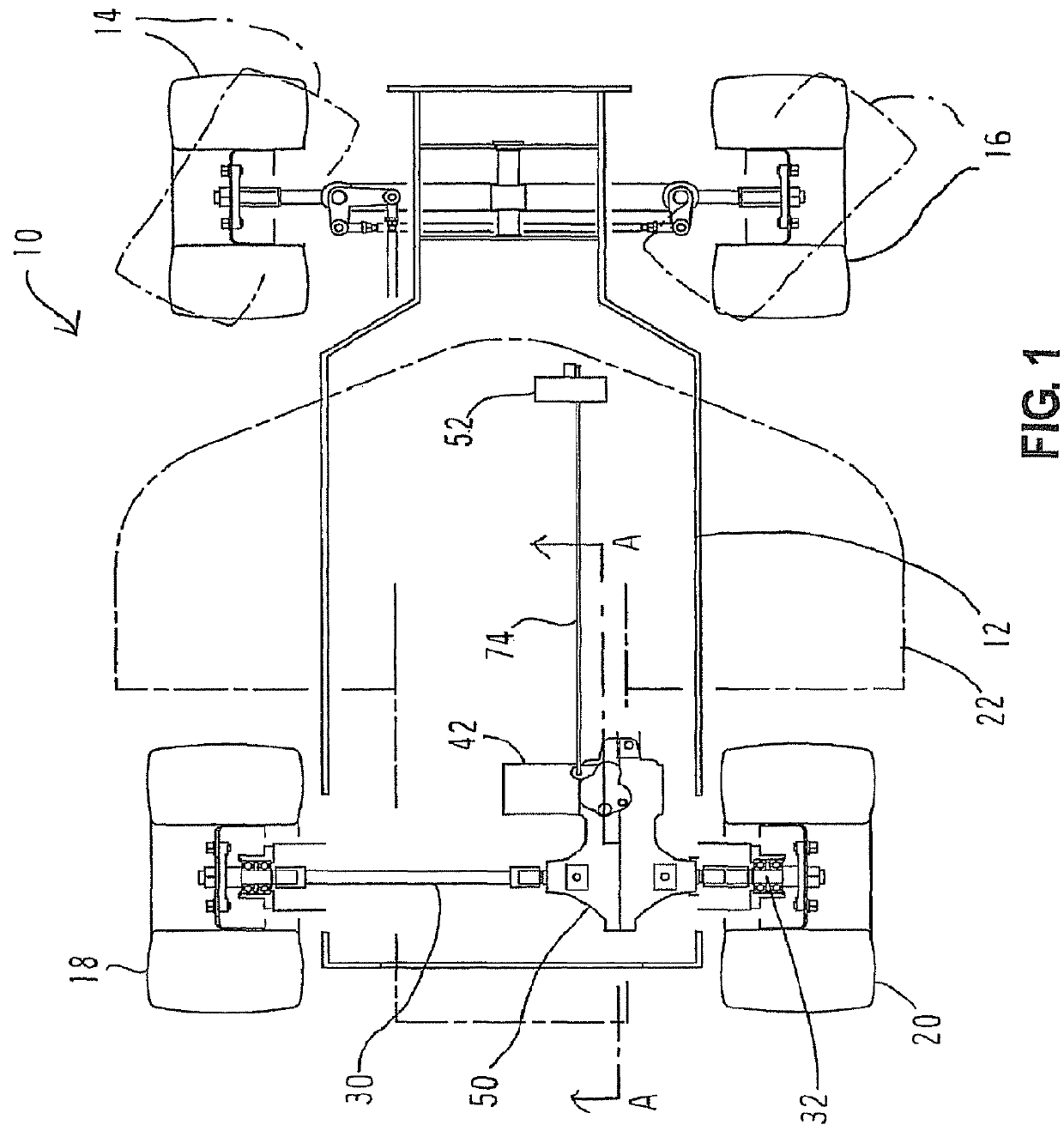
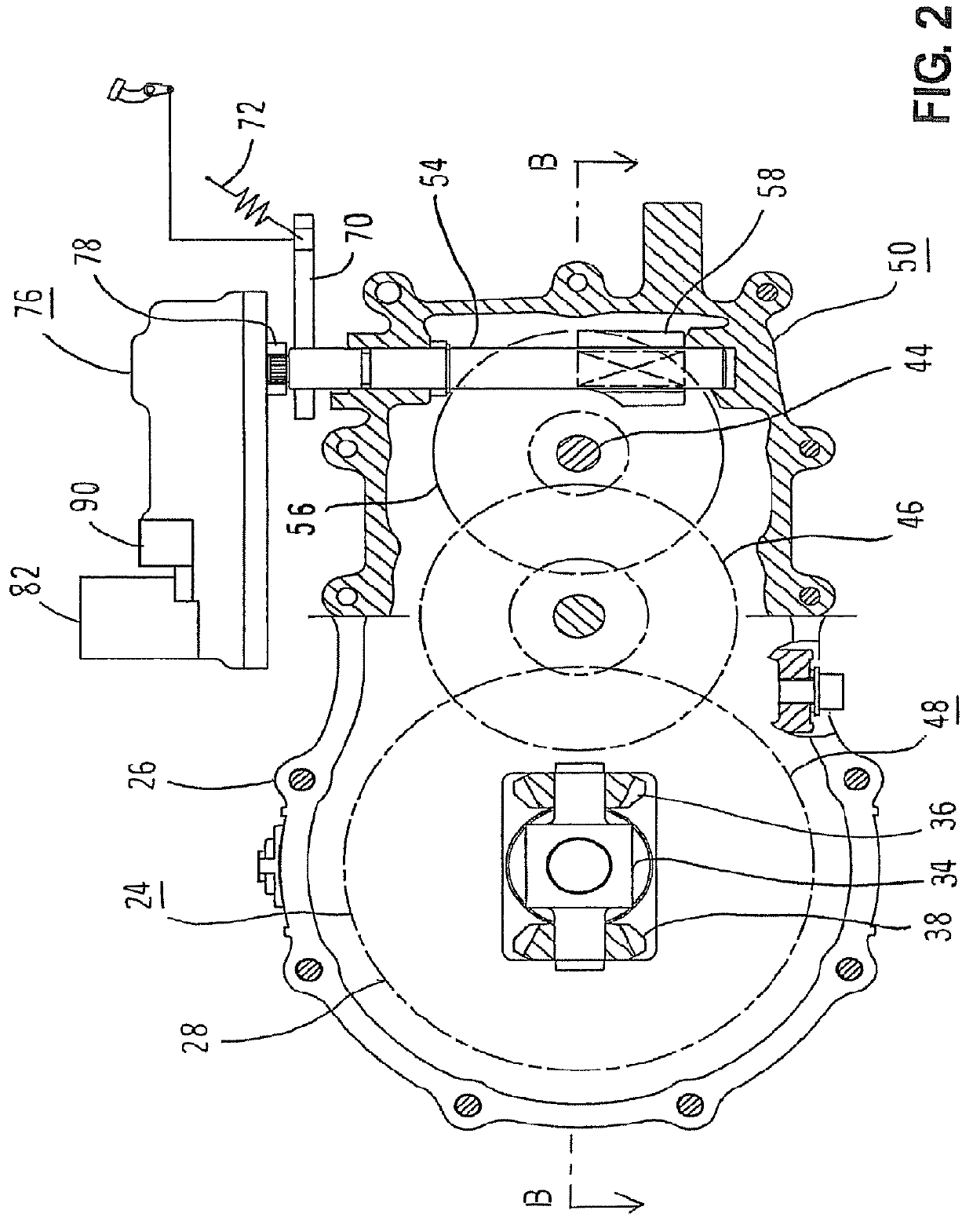
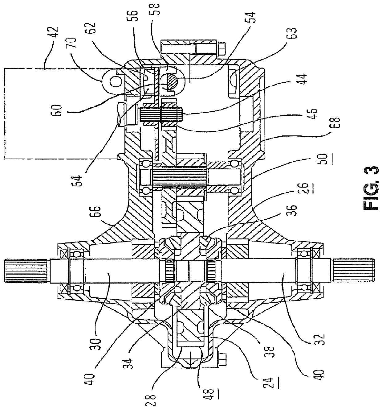
[0061]Embodiments of the present invention will now be described with reference to the drawings. FIGS. 1 through 10 are diagrams showing a first embodiment of the present invention. In the following, the present invention will be described with reference to a case where the present invention is applied to a lawnmower vehicle which is a electric vehicle, but the electric vehicle is not limited to a lawnmower vehicle, and the present invention can be applied to various vehicles in which a wheel is driven by an electric motor. For example, the electric vehicle may be any vehicle in which the wheel is driven by the electric motor other than the lawnmower vehicle, such as ground work vehicles having working machines such as a tiller which are driven for groundwork such as tilling, carriage vehicles such as golf carts used in golf courses, and service vehicles which transport a plurality of passengers. In addition, a drive wheel to be driven by the electric motor is desc...

second embodiment

[Second Embodiment]

[0100]FIG. 11 is a diagram corresponding to FIG. 4 and showing a brake releasing unit 76A in a second embodiment of the present invention. FIG. 12 is an E-E cross sectional view of FIG. 11 showing the brake releasing unit 76A. In the present embodiment, as shown in FIGS. 11 and 12, in the configuration of the first embodiment, the solenoid 90 is fixed at a lower side of the housing 80 so that the shaft portion 126 can be protruded upward from the upper surface of the lower cover 94 of the housing 80. In addition, the shaft portion 126 of the solenoid 90 can be engaged with a plurality of holes 128 placed on the same circumference centered at a central axis on a lower surface of the first intermediate gear 120. The solenoid 90 is driven by supply of electricity, to displace the shaft portion 126 upward, and when the supply of electricity is stopped, the shaft portion 126 is pulled downward by a spring provided inside. When the shaft portion 126 moves downward by it...

third embodiment

[Third Embodiment]

[0101]FIG. 13 is a partial cross sectional view of a brake releasing unit 76B of a third embodiment of the present invention where the shaft portion 126 of the solenoid 90 is opposed to the gear surface of the gear. In the present embodiment, in the configuration of the first embodiment shown in FIGS. 1 through 10, the solenoid 90 is fixed on a side wall section 144 provided on an outer periphery section of the housing 80, to allow the shaft portion 126 to protrude in the lateral direction from the inner surface of the side wall section 144. The shaft portion 126 of the solenoid 90 can enter a region between adjacent teeth sections of the large gear provided on the outer peripheral section of the first intermediate gear 120. By the shaft portion 126 entering the region between the adjacent teeth sections of the large gear, the shaft portion 126 can be engaged with the first intermediate gear 120. The solenoid 90 is driven by supply of electricity, to displace the s...


PUM


Abstract

An electric vehicle comprising a drive wheel which is driven by a traction electric motor, a brake command device, a brake releasing unit, a brake shaft, a friction plate, and a braking spring. The brake shaft is rotatable in a brake realizing direction which is one direction by an operation of the brake command device, and is rotatable in a brake releasing direction which is the other direction by driving of the brake releasing unit. The friction plate is operatively connected to the traction electric motor, and is frictionally braked when the brake shaft is rotated in the brake realizing direction. The braking spring applies an elastic force to the brake shaft in a direction to rotate the brake shaft in the brake realizing direction.

Description

[0001]This application claims the benefit of U.S. Provisional Application No. 61 / 290,075, filed Dec. 24, 2009, the entire disclosure of which is incorporated by reference herein.BACKGROUND[0002]1. Technical Field[0003]The present invention relates to a electric vehicle having a drive wheel which is driven by a traction electric motor, a brake command device which can be operated by a driver, a brake releasing unit which is driven by supplying electricity, a brake shaft, and a friction plate.[0004]2. Related Art[0005]In the related art, a motor-driven structure in which a drive wheel which is a vehicle wheel is driven by a traction electric motor is considered in vehicles such as ground work vehicles having working machines driven for ground work such as lawn mowing and tilling, carriage vehicles such as golf carts used in golf courses, and service vehicles for transporting a plurality of passengers. A electric vehicle which is a vehicle driven by an electric motor is considered to b...

Claims


Application Information

Patent Timeline
Patent Type & Authority Patents(United States)
IPC IPC(8): B60W10/04B60W30/18
CPCB60L3/0076B60L7/24B60L11/1803B60T13/746B60W30/18127B60L7/003B60K2001/001B60L2200/40B60L2240/423B60L2250/24B60L2250/26B60L2260/28B60T2201/04B60Y2200/223Y02T10/642Y02T10/7005B60L50/51Y02T10/64Y02T10/70B60W2540/10B60W2710/083
Inventor IWAKI, KOJIKOGA, KAZUNARISASAHARA, KENGO
Owner KANZAKI KOKYUKOKI MFG
Why Eureka
Try Eureka