Wheel clamping assemblies

a technology for clamping assemblies and wheels, which is applied in the direction of cycle equipment, release mechanisms, steering devices, etc., can solve the problems of unnecessarily complicated, unsatisfactory rigidity of wheel mounting and assembly, and time-consuming, and achieve the effect of reducing the level of complication

Active Publication Date: 2013-02-26
EKO SPORT INC
View PDF18 Cites 26 Cited by
  • Summary
  • Abstract
  • Description
  • Claims
  • Application Information

AI Technical Summary

Benefits of technology

[0019]An object of the present invention is to decrease the level of complication in connecting a bicycle wheel to a bicycle or bicycle fork so that a substantially closed-bore dropout can be used.
[0020]A further object of the present invention is to provide a wheel clamping assembly that enables a substantially closed-bore dropout to be used with an axle assembly that is of a quick-release type and which can be removed quickly without use of specialist tools.
[0021]A further object of the present invention is to provide an improved wheel axle that can be inserted into and removed from a hub in accordance with a simple operation that may be performed by hand and without the need for specialist tools.
[0022]A further object of the present invention is to provide an improved wheel clamping assembly that can be used to secure either a front wheel or a rear wheel of a vehicle such as a one or two-wheeled bicycle or a motorcycle or a tricycle or a motorised trike.
[0036]Preferably said fixing means comprising said slot assembly is of a smaller diameter than the diameter of said axle portion of said axle assembly, said smaller diameter thereby enabling said slot assembly fixing means to pass substantially through a wheel hub.

Problems solved by technology

This known type of system requires use of a tool such as a spanner to release the nuts and is thus time consuming.
Although FR2782471 discloses a quick release wheel hub assembly it may be considered to be unnecessarily complicated in that the bearings are located in the forks rather than in the wheel hub assembly.
A problem with the system disclosed in FR2782471 is that it is highly desirable to use commonly available wheels and wheel hub assemblies wherein the wheel hub itself comprises the bearings, U.S. Pat. No. 5,165,762 also discloses a form of quick release apparatus that comprises a hub having a spindle passing therethrough and to which there is attached a cam lever at a first end and an end cap located at the other end.
However the rigidity of the wheel mounting and assembly is known to be less than optimal.
Although U.S. Pat. No. 6,386,643 provides improved rigidity, the fact that the dropouts are of the open bore type results in less than optimal rigidity as regards the securement of the wheel hub to the forks of the vehicle.
By fully closed bore it is meant a wheel mounting orifice that has a circumference of 360° at all times. However use of such fully closed bore dropouts means that the above mentioned quick release assemblies, as exemplified by U.S. Pat. No. 6,386,643, are not able to be inserted into the dropouts without substantially dismantling the axle assembly and thus losing the intended quick release effect of the quick release assembly.
A problem with the fork / axle assembly schematically illustrated in FIGS. 1 and 2 is that it is difficult and time consuming to remove and replace the axle from / to the open bore dropouts in view of the need to respectively remove and replace the plates.
A further problem is that frequently the bolts or plates may be lost or damaged during removal of a wheel or insertion of a wheel into the fork dropouts.
Without disassembling the QR spindle system for this type of fork / axle assembly (thereby removing the spindle) it is simply not possible to fit the QR axle in to the dropouts.
Although an open bore dropout QR system of the type discussed earlier could be dismantled and then fitted through a closed bore dropout system it would be time consuming and there is the risk of loss of and / or damage to the separated components.
A problem associated with both of the aforementioned Rockshox systems is that, although the axle assembly is fixed to the dropouts, the rigidity of these systems is considered to be less than optimal.
Not only is an alternative required, but the systems designed by Rockshox are considered to be somewhat less than optimal in that the clamping effect of the quick release cams is configured to provide a force on the axle in the direction defined by a radius extending between a point on the circumference of the axle and a point on the longitudinal axis located along the length of and at the centre of the axle.
In the sport of mountain biking high forces (especially as regards front fork systems) may potentially cause the axle in these systems to move, particularly if the cam or cams are not tightened sufficiently or if they become loosened in some way during operation of the bike.
Use of suspension forks can create unbalanced compressional and tensional forces in the fork legs during cornering and manoeuvering of the bicycle.
The known methods for securing larger diameter axles, commonly 20 mm in diameter, differ in design, but each suffers from either requiring specialist tools for the removal of the wheel and / or requires an excessive number of operations to be completed before the wheel can be removed by virtue of the axle being displaced longitudinally through closed-bore dropouts rather than simply being dropped out as is the case with open-bore dropouts.

Method used


Image

  • Wheel clamping assemblies
  • Wheel clamping assemblies
  • Wheel clamping assemblies

Examples


Embodiment Construction

[0055]There will now be described by way of example a specific mode contemplated by the inventors. In the following description numerous specific details are set forth in order to provide a thorough understanding. It will be apparent however, to one skilled in the art, that the present invention may be practiced without limitation to these specific details. In other instances, well known methods and structures have not been described in detail so as not to unnecessarily obscure the description.

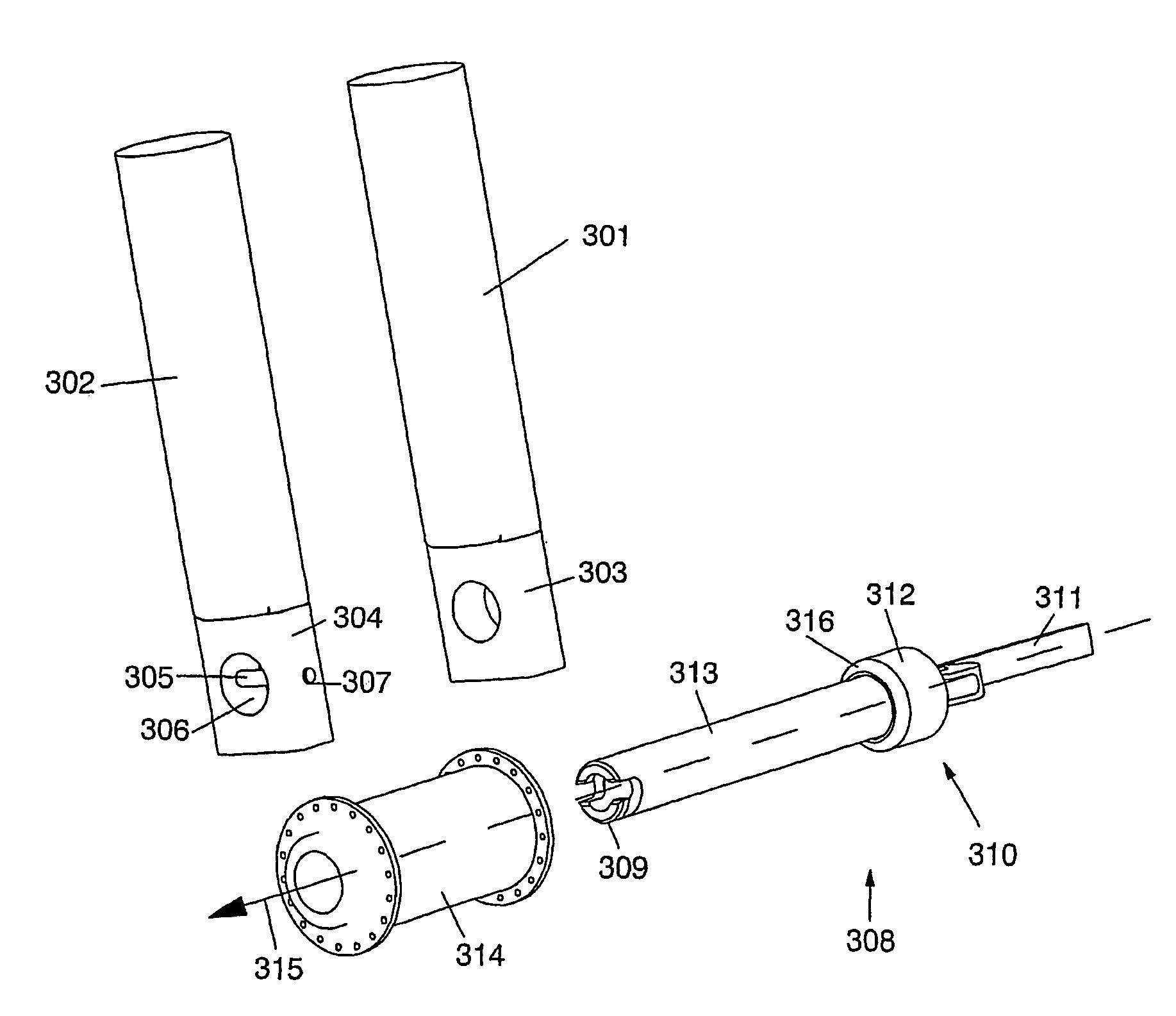
[0056]FIG. 3 schematically illustrates, in exploded perspective view, a wheel clamping assembly in accordance with a preferred embodiment of the present invention. The assembly comprises a pair of forks, such as the front forks of a mountain bike, 301 and 302. The fork legs 301, 302 are elongate and towards the lower end, that is the end to which an axle is to be attached, each fork leg comprises a substantially (full or near) closed bore wheel mounting point 303 and 304 respectively. Fork leg...


PUM


Abstract

An axle assembly (310) has a longitudinal axis and first and second ends, the axle assembly configured for rotatably mounting a wheel and hub assembly on an axle portion or the axle assembly, the axle portion located between the first and second ends, the axle assembly configured for affixing to first and second structural members (301, 302), at least one of the structural members (302) comprising a substantially closed bore orifice (306) wheel mounting point or dropout, said dropout having a first side configured for the axle portion to extend therefrom when said axle assembly (310) is fixed to said point and a second side, the axle assembly (310) comprising a first fixing means (309) at the first end for releasably fixing the axle assembly (310) to the first structural member (302) and a second fixing means (311) at the second end fog releasably fixing the axle assembly (310) to the second structural member (301).

Description

CROSS-REFERENCES TO RELATED APPLICATIONS[0001]This application is a submission to enter the national stage under 35 U.S.C. 371 for international application number PCT / GB2005 / 002268 having international filing date Jun. 8, 2005, for which priority was based upon patent application 0412858.3 having a filing date of Jun. 9, 2004 filed in Great Britain.FIELD OF THE INVENTION[0002]The present invention relates to wheel clamping assemblies for use in fixing an axle to a structure and particularly, although not exclusively, the invention relates to a quick release axle for use in fixing a wheel to a vehicle such as a bicycle or a motorcycle.BACKGROUND TO THE INVENTION[0003]Fixing devices for securing a wheel to a structure are known. Thus, for example, bicycle wheels, motorcycle wheels, trike wheels and wheels of karts, prams and the like are known to be secured by a wide variety of types of fixing devices. In the field of bicycles and motorcycles it is known to secure a wheel to a set of...

Claims


Application Information

Patent Timeline
Patent Type & Authority Patents(United States)
IPC IPC(8): B62K25/02
CPCB62K25/02B60B35/004B62K2206/00B60B27/026
Inventor BARTLETT, SIMON CHARLESHART, NICHOLAS ANDREW
Owner EKO SPORT INC
Why Eureka
Try Eureka