Sensor arrangement

a technology of sensors and insulating pads, applied in the field of sensor devices, can solve the problems of reduced breathability of these locations, loose electrical conductors on the surface of fabric, and discomfort of skin, and achieve the effect of convenient manufacturing

Active Publication Date: 2013-02-26
SUUNTO OY
View PDF28 Cites 122 Cited by
  • Summary
  • Abstract
  • Description
  • Claims
  • Application Information

AI Technical Summary

Benefits of technology

[0010]The invention is intended to eliminate the defects of the state of the art disclosed above and for this purpose create a new type of flexible sensor, which is manufactured on a textile substrate, and which is reliable and easily manufactured.

Problems solved by technology

However, the laminate then remains on the surface of the product at the conductors, so that the breathability of these locations is reduced and they may feel uncomfortable against the skin.
This solution also has a problem with the placing of the signal transmission conductors relative to the fibre material, particularly with creating both reliable contacts with the electrodes for them and good electrical insulation.
However, the electrical conductors remain loose of the surface of the fabric and liable to mechanical stresses acting on them.
Though it can be attached to many different pieces of apparel, it does not eliminate the problem of discomfort when using traditional heart rate bands.

Method used


Image

  • Sensor arrangement
  • Sensor arrangement
  • Sensor arrangement

Examples


Embodiment Construction

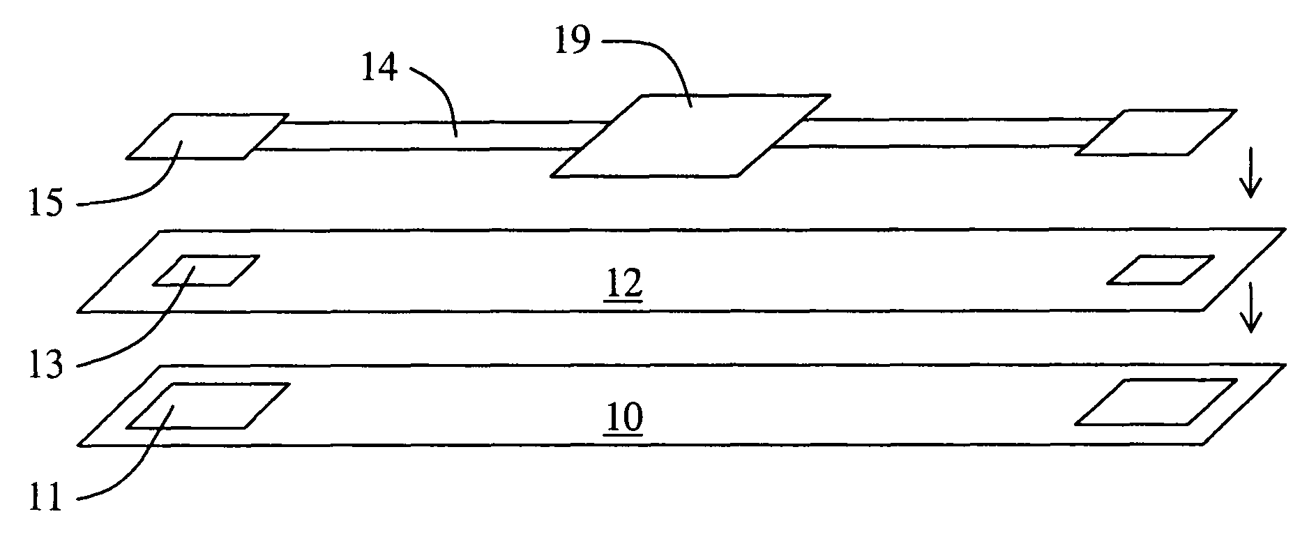
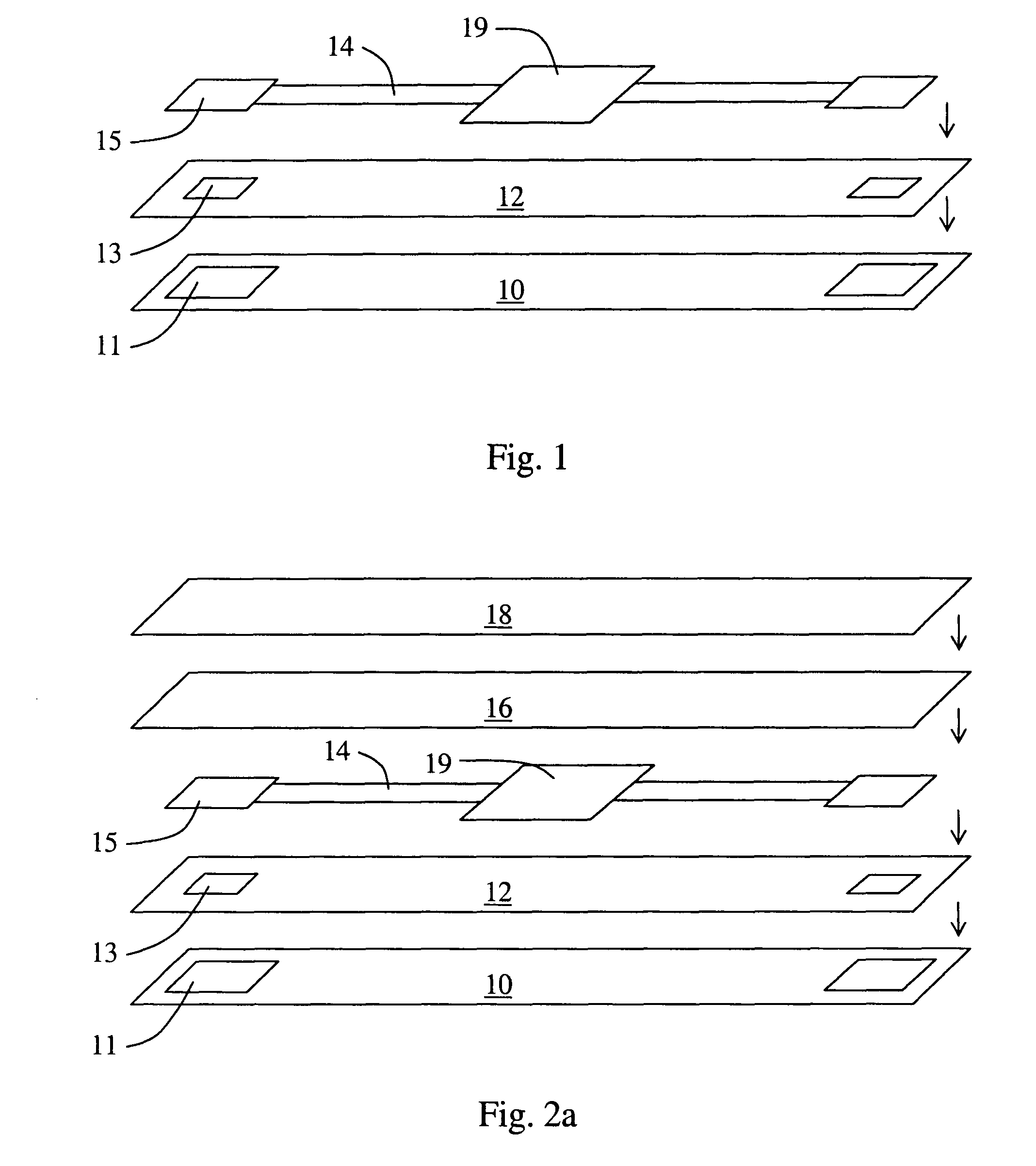
[0026]In FIG. 1, the substrate is marked with the reference number 10. An opening 11 is made in it for an electrode contact. A moisture-insulating intermediate layer 12 is attached permanently on top of the substrate. An opening 13, which can essentially coincide with the opening 11 can also be made in the intermediate layer. The openings 11 and 13 can, of course, also be made later in a single work stage. The electrode 15 is positioned relative to the opening 11 in the substrate and to the opening 13 in the intermediate layer, so that there is a contact connection to its signalling surface from the outer surface of the substrate 10 (from the skin). The signal transmission conductor 14 is attached on top of the intermediate layer 12. Thus the signal transmission conductor 14 is attached to the substrate 10 with the aid of the electrically insulating and watertight layer 12, which is located between the strip-like signal transmission conductor 14 and the substrate 10. At one end, the...


PUM

PropertyMeasurementUnit
elongationsaaaaaaaaaa
flexibleaaaaaaaaaa

Abstract

A sensor for measuring a physiological signal and a method for manufacturing such a sensor. Such a sensor includes a flexible substrate and at least one electrode, which has a signalling surface, which faces in the same direction as the first surface of the flexible substrate. In addition, the sensor includes a signal transmission conductor, which is connected electrically to the electrode. The signal transmission conductor is attached in a watertight manner to the second surface of the substrate. The sensor is reliable, economical to manufacture, and comfortable to the user.

Description

[0001]The present application claims priority to FI 20065391, filed in Finland on Jun. 8, 2006, which designated the United States, and on which priority is claimed under 35 U.S.C. §120, the entire contents of which are hereby incorporated by reference.BACKGROUND OF THE INVENTION[0002]1. Field of the Invention[0003]The present invention relates to sensor devices. In particular the invention relates to new sensor for measuring a physiological signal from the skin. Such sensor typically comprises a substrate, a signal electrode, and means from transmitting a signal electrically. In addition, the invention relates to a method for manufacturing sensor, to a heart rate belt, and to apparel.[0004]2. Description of Background Art[0005]Traditional heart-rate meter heart rate bands and heart rate belts generally comprise a body made of plastic, on the surface of which there are two local electrodes to be placed against the chest. Electronics for transmitting a heart rate signal, typically to...

Claims


Application Information

Patent Timeline
Patent Type & Authority Patents(United States)
IPC IPC(8): A61B5/0408
CPCA61B5/0245A61B5/04A61N1/22Y10T29/4913A61B5/6831A41D13/1281A61B5/02438
Inventor LINDBERG, PHILLIPPERNU, KIMMOMANNI, JUKKALILJEMARK, JORMASAVOLAINEN, TAPIOPUTKINEN, HANNUAKKILA, JARIRAHKONEN, SATULINDMAN, ERIK
Owner SUUNTO OY
Why Eureka
Try Eureka