Image falsification detection device and image falsification detection method
a detection device and image technology, applied in the field of image falsification detection devices and image falsification detection methods, can solve problems such as burdening users
- Summary
- Abstract
- Description
- Claims
- Application Information
AI Technical Summary
Benefits of technology
Problems solved by technology
Method used
Image
Examples
first embodiment
[First Embodiment]
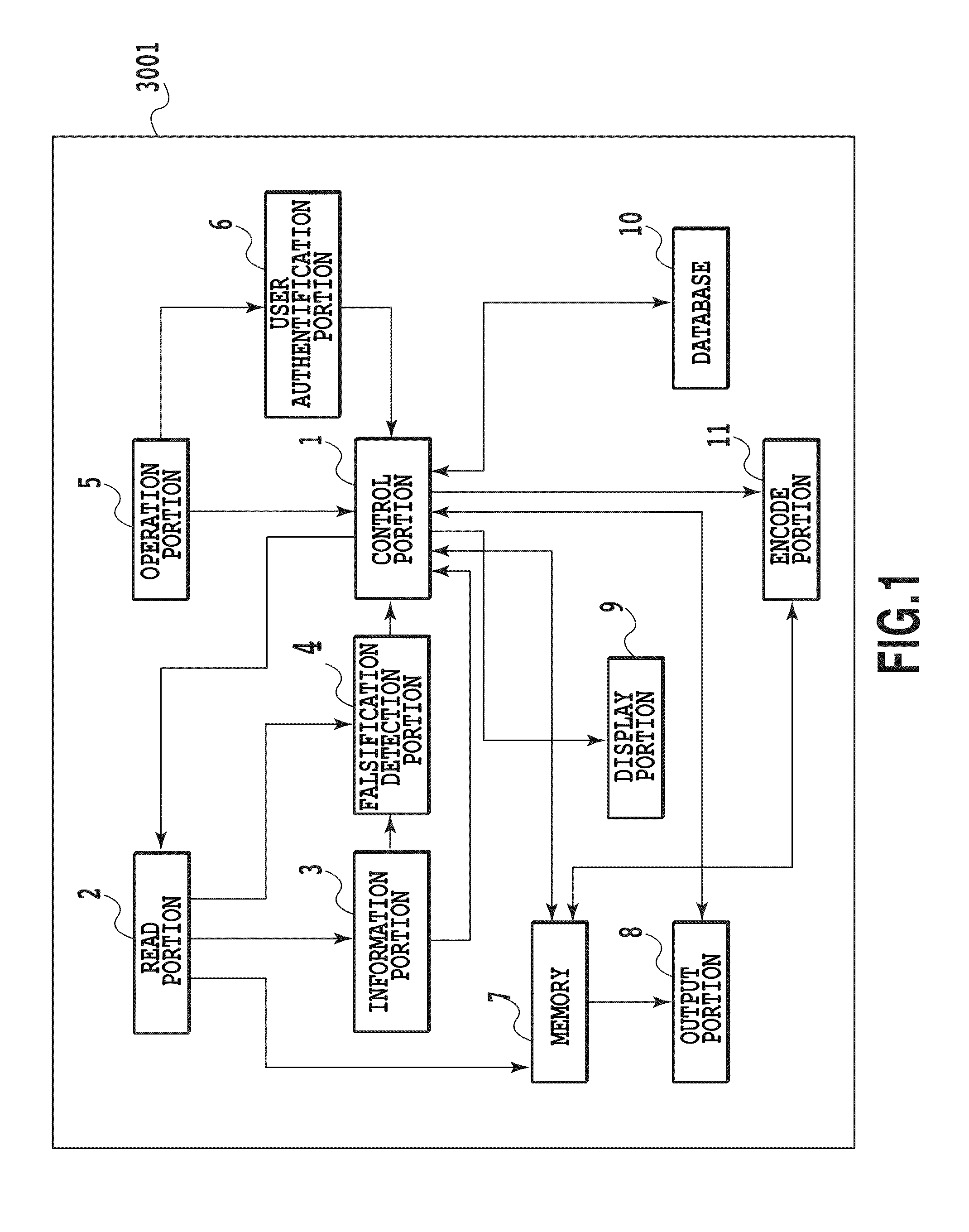
[0036]FIG. 1 is a block diagram showing the configuration of an image forming device (MFP3001 as one example thereof) in the present embodiment.
[0037]A control portion 1 controls the respective portions of MFP3001, which is one example of the image forming device in the present embodiment. An operation portion 5 receives an operation / input from a user. A user authentification portion 6 manages the user authentification of a user who uses MFP3001. A read portion 2 scans a printed material to generate read information including falsification detection code information. An information portion 3 acquires information embedded in the printed material from the falsification detection code information included in the read information. A falsification detection portion 4 decodes falsification detection information from the information embedded in the printed material, and detects whether or not document information for an original document image is falsified.
[0038]A memory ...
second embodiment
[Second Embodiment]
[0081]Next, a second embodiment will be described with reference to the accompanying drawings. Among the drawings referenced in the present embodiment, the description of the configuration diagrams and the flowcharts already discussed in the first embodiment will be omitted. The present embodiment differs from the first embodiment in the falsification detection processing in step S211 shown in FIG. 2, and the second embodiment will be described with reference to FIG. 10 showing the detailed flow therefor.
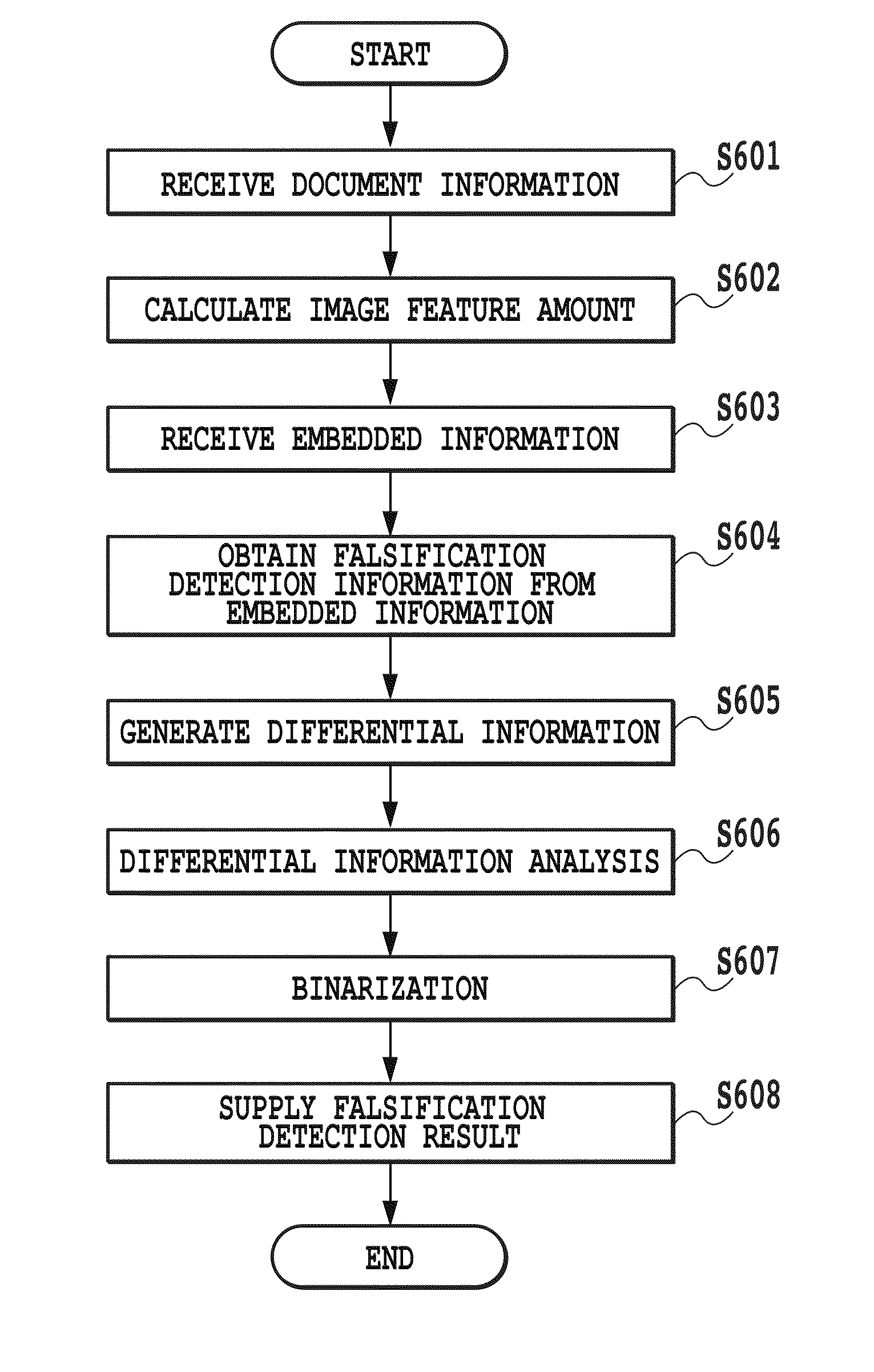
[0082]Since the processing performed in steps S601 to S605, S607 and S608 shown in FIG. 10 is the same as in the first embodiment, its description will be omitted. After the differential information is generated, the falsification detection portion 4 determines the degree of deterioration of the read information obtained by the scanning (S1001). If the degree of deterioration is determined to be large, the process proceeds to step S1002 whereas, if the degree of d...
third embodiment
[Third Embodiment]
[0096]Next, a third embodiment will be described with reference to the accompanying drawings. Among the drawings referenced in the present embodiment, the description of the configuration diagrams and the flowcharts already discussed in the first embodiment will be omitted. The third embodiment differs from the first embodiment in the differential information analysis processing in step S606, and the third embodiment will be described with reference to FIG. 12 showing the detailed flow for the differential information analysis in step S606.
[0097]Since the processing performed in steps S801 to S803 among the processing of the flowchart shown in FIG. 12 is the same as in the first embodiment, its description will be omitted.
[0098]In step S1201, the falsification detection portion 4 calculates a threshold value correction amount by the use of an error correction ratio of the falsification detection code in each of the division regions divided by the processing in S801...
PUM
 Abstract
Description
Claims
Application Information
 - R&D
- Intellectual Property
- Life Sciences
- Materials
- Tech Scout
- Unparalleled Data Quality
- Higher Quality Content
- 60% Fewer Hallucinations
Browse by: Latest US Patents, China's latest patents, Technical Efficacy Thesaurus, Application Domain, Technology Topic, Popular Technical Reports.
© 2025 PatSnap. All rights reserved.Legal|Privacy policy|Modern Slavery Act Transparency Statement|Sitemap|About US| Contact US: help@patsnap.com


