Sheet conveying apparatus and image forming apparatus

a conveying apparatus and a technology of forming apparatus, applied in the direction of registering devices, thin material processing, article separation, etc., can solve the problems of increasing inhibiting further improvement in throughput, increasing etc., to increase the sheet gap distance, improve throughput, and increase the sheet conveying speed

Inactive Publication Date: 2013-03-05
CANON KK
View PDF11 Cites 24 Cited by
  • Summary
  • Abstract
  • Description
  • Claims
  • Application Information

AI Technical Summary

Benefits of technology

[0009]The present invention provides a sheet conveying apparatus inhibiting an increase in sheet gap distance while increasing a sheet conveying speed to improve throughput, and an image forming apparatus having the same.
[0011]The present invention can shorten the time needed from when the sheet passes to when the rotation detection portion is positioned in the standby position, thereby reducing the need to secure a long distance required for a sheet gap distance and thus improving throughput.

Problems solved by technology

Thus, the conventional sheet detection device has a problem in that an increase in the sheet conveying speed increases the sheet gap distance, which inhibits further improvement in throughput.

Method used


Image

  • Sheet conveying apparatus and image forming apparatus
  • Sheet conveying apparatus and image forming apparatus
  • Sheet conveying apparatus and image forming apparatus

Examples


first embodiment

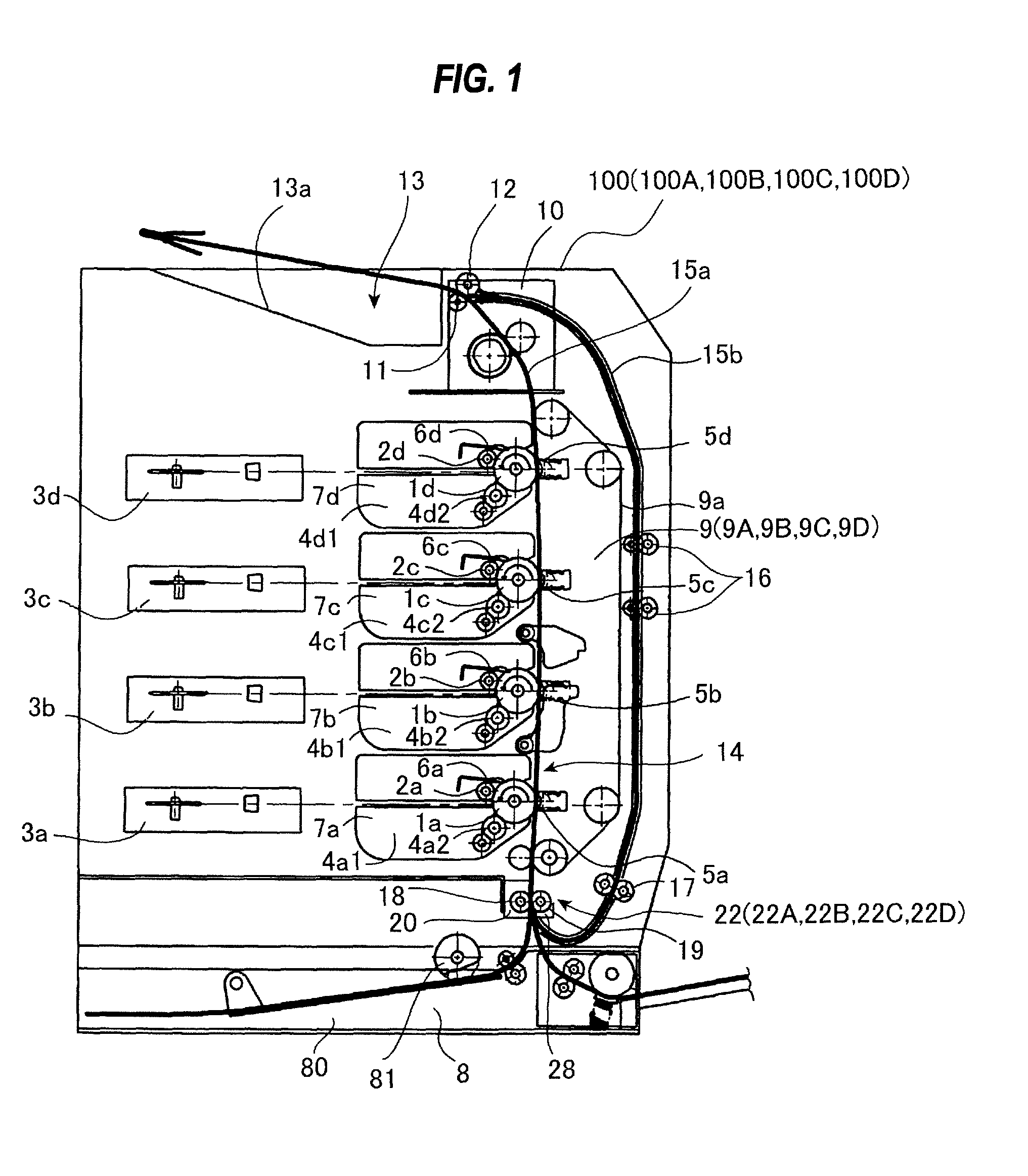
[0097]The image forming apparatus 100 according to a first embodiment of the present invention will be described referring to FIGS. 1 to 10D. First, referring to FIG. 1, an entire structure of the image forming apparatus 100 according to the first embodiment will be described. FIG. 1 is a sectional view schematically illustrating the entire structure of the image forming apparatus 100 according to the first embodiment of the present invention.

[0098]As illustrated in FIG. 1, the image forming apparatus 100 according to the first embodiment includes: a sheet feeding portion 8 feeding a sheet S; an image forming portion 14 forming a toner image; a fixing portion 10 fixing a transferred unfixed toner image; and a sheet conveying portion 9 as a sheet conveying apparatus. Further, the image forming apparatus 100 includes a sheet discharging portion 13 discharging the sheet S with the toner image fixed thereon.

[0099]The sheet feeding portion 8 includes: a paper feed cassette 80 storing she...

second embodiment

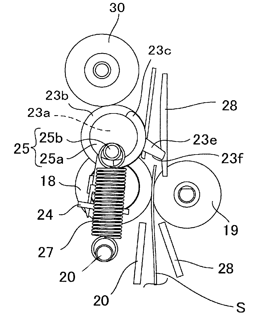
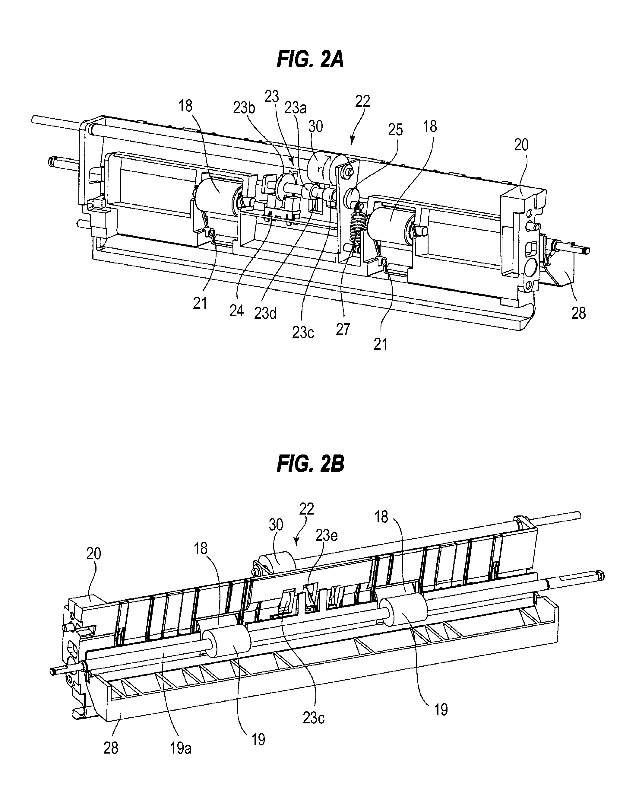
[0135]An image forming apparatus 100A according to a second embodiment of the present invention will be described referring to FIGS. 11 to 14D. FIG. 11 is a perspective view illustrating a sheet detection portion 22A supported by a paper feed frame 20 according to the second embodiment. FIG. 12 is a perspective view illustrating a sensor flag 23A of the sheet detection portion 22A according to the second embodiment. FIG. 13A illustrates the sheet detection portion 22A according to the second embodiment. FIG. 13B illustrates an assist cam 23c and a rotation assist roller 30 in a state illustrated in FIG. 13A. FIG. 13C illustrates an abutting portion 223e of a shutter flag 223a in a state illustrated in FIG. 13A. FIG. 13D illustrates a light shielding portion 23b in a state illustrated in FIG. 13A.

[0136]FIG. 14A illustrates a state in which the abutting portion 223e of the shutter flag 223a abuts against a sheet S and enters a wait state. FIG. 14B illustrates the assist cam 23c and th...

third embodiment

[0144]Referring to FIG. 1 and further referring to FIGS. 15 to 22C, an image forming apparatus 100B according to the third embodiment of the present invention will be described. FIG. 15 is a perspective view illustrating a sheet detection portion 22B supported by a paper feed frame 20 according to the third embodiment. FIG. 16 is a perspective view illustrating a sensor flag 23B of the sheet detection portion 22B according to the third embodiment. FIG. 17A illustrates the sheet detection portion 22B according to the third embodiment. FIG. 17B illustrates a sensor cam 323i, a shutter spring 327, a cam follower 336, and a pressing member 335 in a state illustrated in FIG. 17A. FIG. 17C illustrates an abutting portion 323a and a light shielding portion 323b of a shutter flag 323 in a state illustrated in FIG. 17A. FIG. 18A illustrates a state in which the sensor flag 23B rotates to shield an optical path of an optical sensor. FIG. 18B illustrates the sensor cam 323i, the shutter spring...


PUM


Abstract

A sheet conveying apparatus including, a conveying portion conveying a sheet; a rotation detection portion rotatably provided; a sensor portion detecting the conveyed sheet based on a rotational position of the rotation detection portion; a rotation transmission portion transmitting a rotational driving force to the rotation detection portion to rotate the rotation detection portion in a predetermined rotational direction after the rotation detection portion is rotated by being pushed by the leading end of the sheet; and an urging unit configured to apply an urging force to the rotation detection portion so that the rotation detection portion comes into contact with a surface of the sheet, thereafter the rotation detection portion is returned to a waiting position along with the passage of the rear end of the sheet through the rotation detection portion after the rotation detection portion is rotated by the rotational driving force of the rotation transmitting unit.

Description

BACKGROUND OF THE INVENTION[0001]1. Field of the Invention[0002]The present invention relates to a sheet conveying apparatus and an image forming apparatus having the same, and more particularly to an image forming apparatus having a sheet conveying apparatus which can detect a leading end position of a sheet to be conveyed.[0003]2. Description of the Related Art[0004]In general, the image forming apparatus provides a sheet conveying portion with a sheet detection portion detecting a leading end position of a sheet in order to match the time to send the sheet to an image transfer position with the time to send an image (toner image) to the image transfer position. The image forming apparatus provides the sheet conveying portion with a plurality of sheet detection portions to detect a sheet conveying state along a sheet conveying path such as a sheet conveyance delay and a jam (see Japanese Patent Application Laid-Open No. H09-183539).[0005]FIGS. 30 to 31B illustrate a conventionally...

Claims


Application Information

Patent Timeline
Patent Type & Authority Patents(United States)
IPC IPC(8): B65H9/04B65H7/02B65H43/00
CPCB65H7/02B65H2404/14B65H2801/06B65H2553/612B65H2701/1311B65H2553/412B65H2553/61
Inventor SUZUKI, YOHEI
Owner CANON KK
Why Eureka
Try Eureka