
System and method for measuring blood viscosity

a blood viscosity and blood technology, applied in the field of non-invasive techniques, can solve the problems of inability to accurately measure the blood viscosity, the procedure is complicated, and the patient is undesirable, and the technique may not provide accurate results. achieve the effect of accurate and non-invasive blood viscosity measuremen

Active Publication Date: 2013-03-05
GENERAL ELECTRIC CO
View PDF6 Cites 26 Cited by
  • Summary
  • Abstract
  • Description
  • Claims
  • Application Information

AI Technical Summary

Benefits of technology

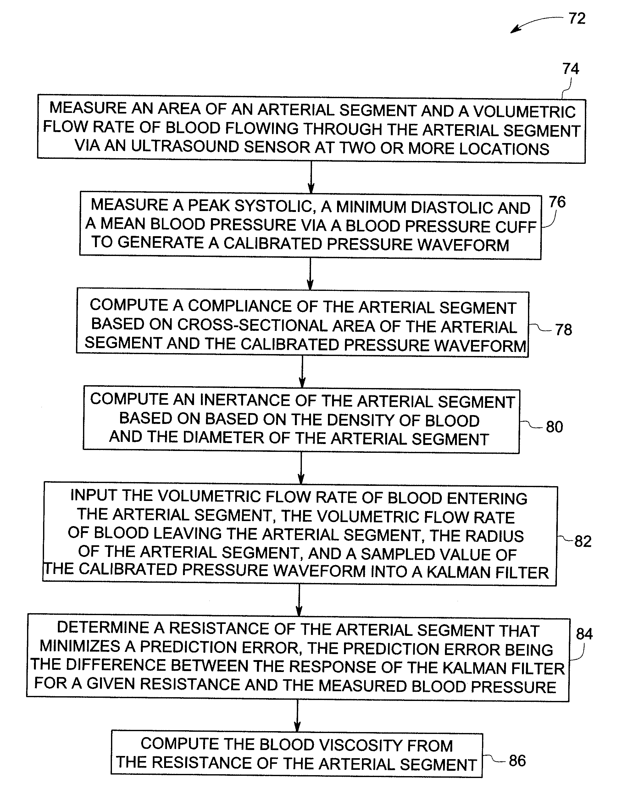
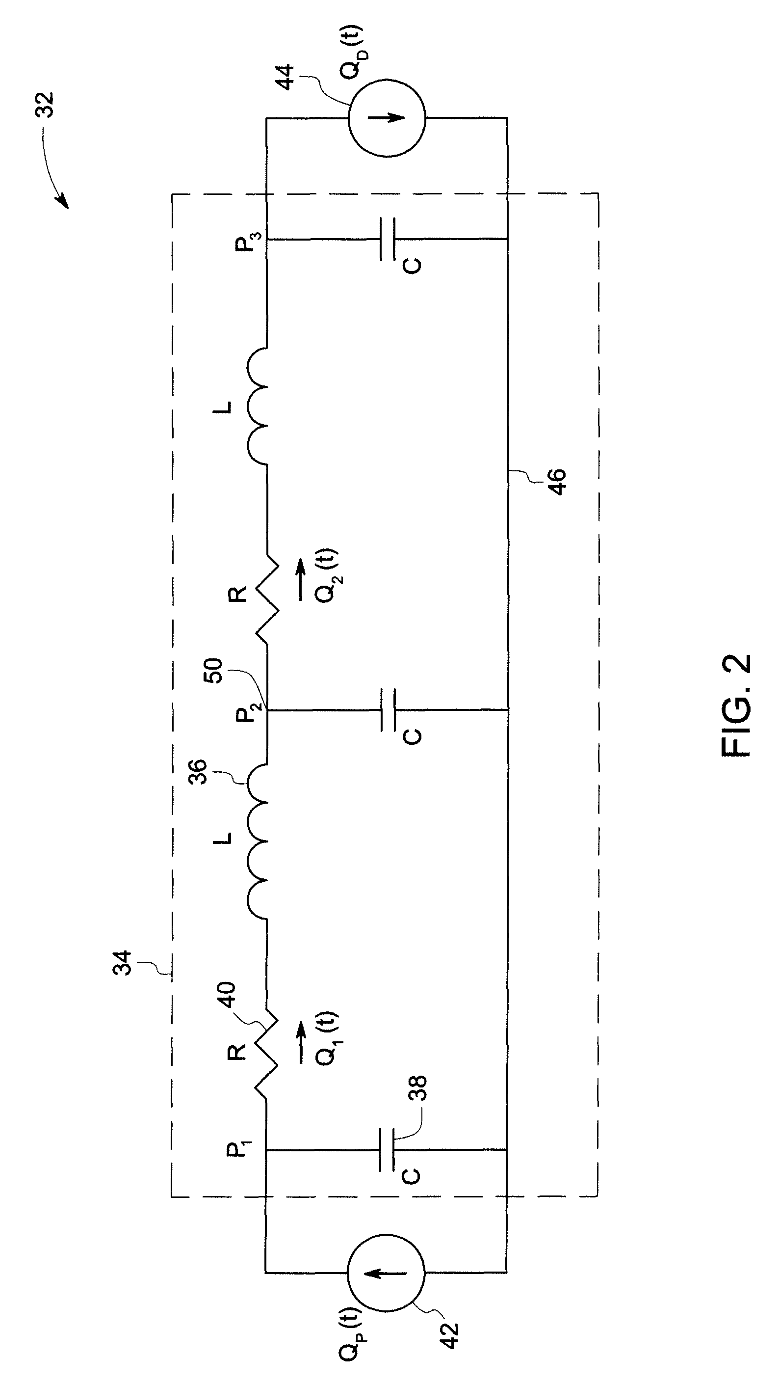
The patent describes a method and system for measuring and monitoring blood viscosity. The method involves measuring the cross-sectional area and flow rate of blood in an arterial segment using ultrasound sensors and a blood pressure cuff. An estimated compliance function is then derived based on the measured pressure and the known density of blood. This function is then used to compute the blood viscosity using a transmission line model. The system includes ultrasound sensors and a blood pressure cuff, along with a processor that derives a transmission line model and computes the blood viscosity based on the measured data. The technical effects of this patent include improved accuracy in measuring blood viscosity and the ability to monitor blood viscosity in real-time.

Problems solved by technology

However, these techniques require drawing blood from the patient by making an incision into the patient's skin.
This invasive procedure is complicated, painful, and therefore undesirable to the patient.
However, these techniques may not provide accurate measurement of the blood viscosity, as the parameters governing the viscosity measurement are themselves susceptible to measurement errors on account of various factors such as changes in the physiological state of the patient, elastic nature of the arterial, technique employed to measure the respective parameter, and so forth.

Method used


Image

  • System and method for measuring blood viscosity
  • System and method for measuring blood viscosity
  • System and method for measuring blood viscosity

Examples


Embodiment Construction

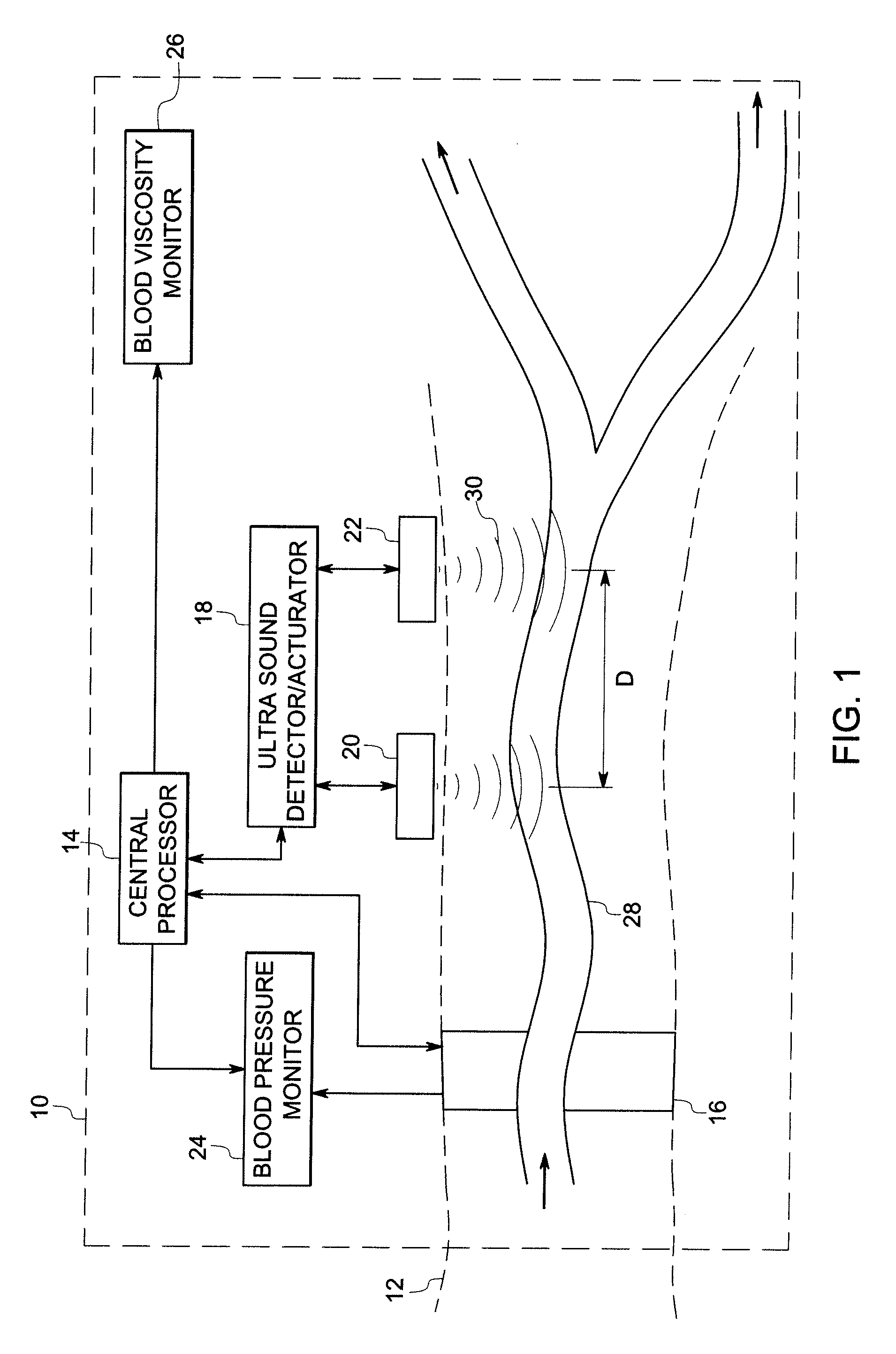
[0015]Referring now to FIG. 1, a blood viscosity measurement and monitoring system 10 is illustrated in accordance with aspects of the present technique. As will be appreciated by one skilled in the art, in certain embodiments, the blood viscosity measurement and monitoring system 10 may be part of an overall patient monitoring system that may provide medical personnel with information regarding different physiological parameters of a patient 12. The patient monitoring system may additionally include an electrocardiograph (ECG), a pulse oximeter, and a blood pressure measurement and monitoring system.

[0016]In the co-pending application Ser. No. 11 / 083,259, a method for continuous, noninvasive blood pressure estimation is taught that uses a very similar signal processing approach to that of the present invention. In that invention, the blood pressure estimation algorithm is occasionally re-calibrated by inflating the blood pressure cuff, and during these re-calibrations, the blood vi...


PUM


Abstract

A technique is provided for computing or monitoring blood viscosity. The technique includes measuring a cross sectional area of a arterial segment and a volumetric flow rate of blood flowing through the arterial segment at two or more locations, estimating a compliance transfer function from blood measurements to scale the arterial cross sectional area into a pressure waveform, deriving a transmission line model of the arterial segment based on the cross sectional area, as scaled by the compliance transfer function, of the arterial segment at the two or more locations and the volumetric flow rate of blood at the two or more locations. The technique also includes computing the blood viscosity based on the transmission line model.

Description

CROSS REFERENCE TO RELATED APPLICATIONS[0001]This application is a Continuation-in-Part of U.S. patent application Ser. No. 11 / 083,259, entitled “CONTINUOUS, NON-INVASIVE TECHNIQUE FOR DETERMINING BLOOD PRESSURE USING A TRANSMISSION LINE MODEL AND TRANSCUTANEOUS ULTRASOUND MEASUREMENTS”, by Ralph T. Hoctor et al. filed on Mar. 17, 2005, which is herein incorporated by reference.BACKGROUND[0002]The invention relates generally to a technique of measuring blood viscosity, and more particularly to a non-invasive technique of measuring blood viscosity using an arterial transmission line model.[0003]Blood viscosity is an important physiological parameter for evaluating the condition of a patient. For example, blood viscosity is indicative of the hematocrit level of the patient. It is also helpful in predicting diseases such as diabetes, hypertension, infections, and infarctions. Additionally, it is of interest to monitor blood viscosity in the patient receiving antiplatelet drugs. Traditi...

Claims


Application Information

Patent Timeline
Patent Type & Authority Patents(United States)
IPC IPC(8): A61B5/02A61B8/00
CPCA61B5/02125A61B5/022A61B8/04A61B8/06A61B8/13A61B8/4236A61B8/4472A61B5/02035A61B8/0891A61B8/4477A61B8/4483A61B8/488A61B8/5223A61B8/543A61B8/58G16H50/30
Inventor HOCTOR, RALPH THOMASDENTINGER, AARON MARK
Owner GENERAL ELECTRIC CO
Learn More