
Single period phase to digital converter

a digital converter and single-period technology, applied in the field of electronic circuits, can solve the problem of delay of phase correction by one reference clock cycl

Inactive Publication Date: 2013-03-05
NXP USA INC
View PDF14 Cites 20 Cited by
  • Summary
  • Abstract
  • Description
  • Claims
  • Application Information

AI Technical Summary

Benefits of technology

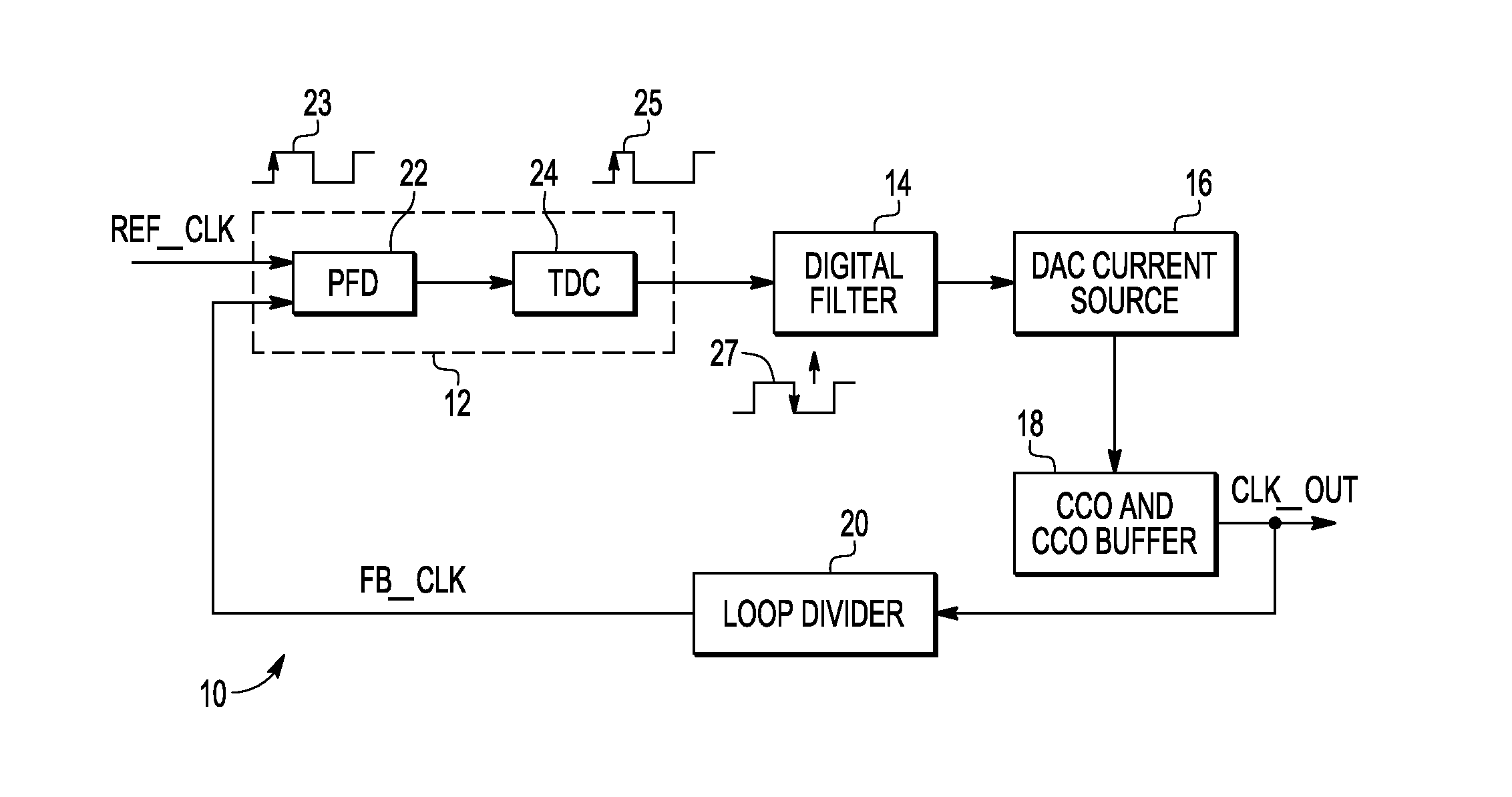
The present invention relates to a digital phase lock loop (PLL) with a phase to digital converter (PDC) and a faster output phase to digital converter (FOPDC) for faster correction of phase error information by a digital PLL. The invention aims to address the issue of delayed correction in conventional fully digital PLLs and to provide a faster and more efficient solution for faster phase error correction. The technical effects of the invention include faster phase correction, improved accuracy, and reduced latency in the correction process.

Problems solved by technology

Additionally, noise susceptible analog control of the controlled oscillator in an analog PLL can be replaced with inherent noise immune digital control for the controlled oscillator in a digital PLL.
However, existing PLLs that are completely digital provide phase to digital converter outputs at each rising edge of the reference clock based on the phase difference information obtained from the previous reference clock cycle and therefore, phase correction is delayed by one reference clock cycle.

Method used


Image

  • Single period phase to digital converter
  • Single period phase to digital converter
  • Single period phase to digital converter

Examples


Embodiment Construction

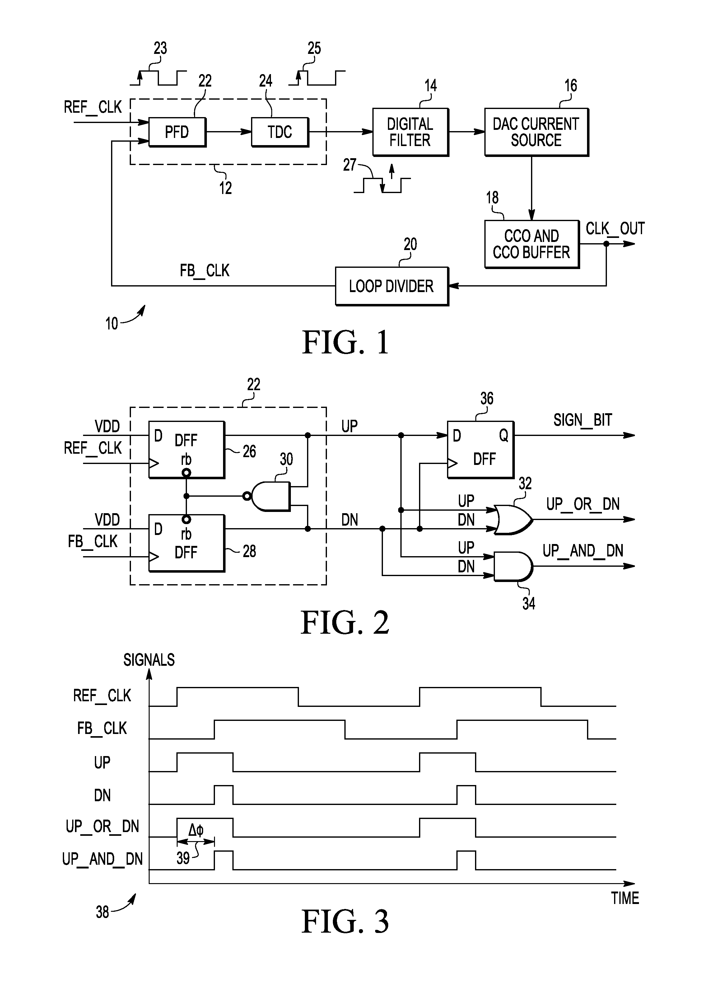
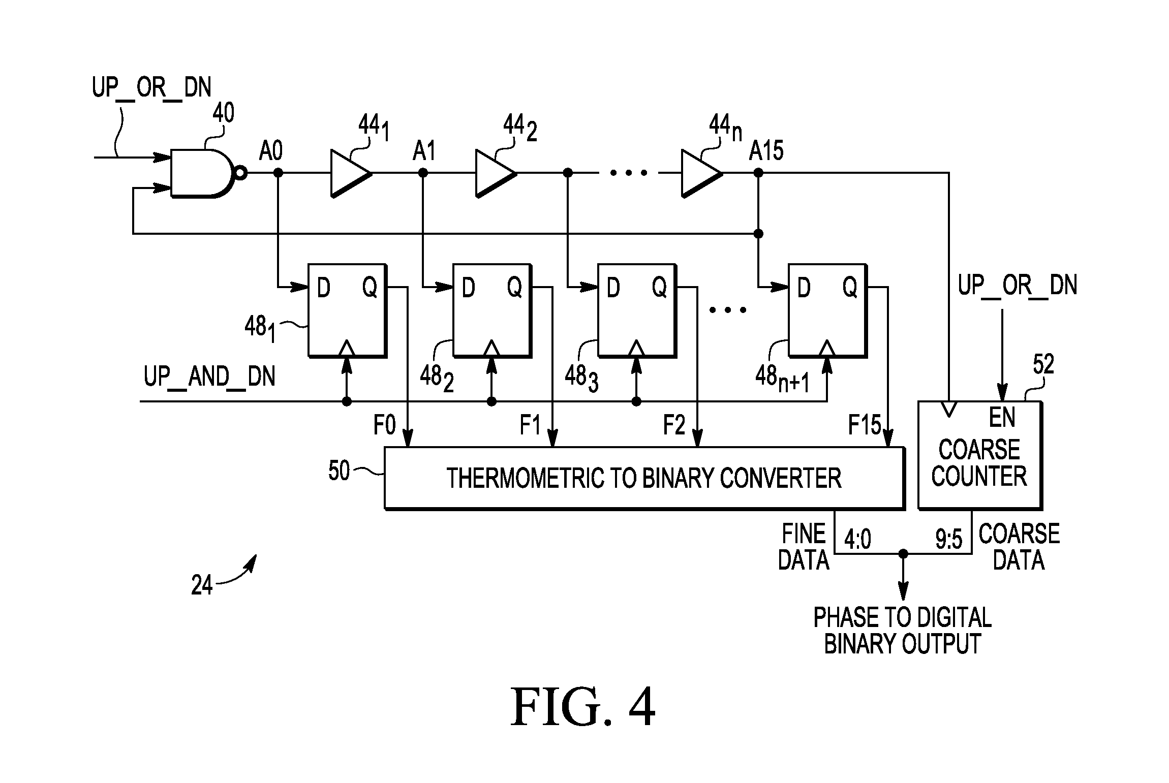
[0022]A phase to digital converter (PDC), method and phase locked loop (PLL) are disclosed. The PDC provides an output in a single reference clock cycle for which the PDC is digitizing phase difference information. A digital filter of the PLL operates on the negative edge of the reference clock so the PLL corrects the phase difference in the same reference clock cycle for which the PDC is digitizing the phase difference information. Since there is no added delay in the signal path (the PLL is correcting phase for the current phase difference between the reference cycle and feedback cycle), and the delay is reduced to a single reference clock period, the loop dynamics and stability of the PLL are readily modelled.

[0023]In one embodiment, the present invention provides a phase locked loop for generating an oscillator signal. A phase to digital converter receives a reference clock and a feedback clock, and generates a digital output signal of a phase error difference between the refere...


PUM


Abstract

A phase to digital converter for a digital PLL (Phase Locked Loop) provides an output in the same or single reference clock period for which it is digitizing the phase error information. The phase to digital converter operates on a positive edge of the reference clock and a digital filter operates on the negative edge of the reference clock so the phase correction performed by the PLL occurs in the same reference clock cycle in which the phase to digital converter is digitizing the phase error information.

Description

BACKGROUND OF THE INVENTION[0001]The present invention relates generally to electronic circuits including a phase to digital converter, and more particularly to a digital phase-locked loop (PLL) with a phase to digital converter.[0002]A PLL is a control system useful in electronic devices such as radios, computers, telecommunication equipment and the like. The PLL contains a phase frequency detector (PFD) and a controlled oscillator, and traditionally is constructed using a combination of both digital and analog circuitry. The PFD compares the frequencies of an input reference clock and a feedback clock and generates a phase difference of the two input frequencies as an output. If the two input frequencies differ, the PFD generates a periodic output proportional to the difference of frequency / phase. If the reference clock frequency differs from the feedback clock frequency, a phase-error signal is generated and filtered and used to cause the feedback clock to shift and lock-in to ma...

Claims


Application Information

Patent Timeline
IPC IPC(8): H03L7/06
CPCH03L7/085H03L7/1077H03L7/089
Inventor SINHA, ANAND KUMARWADHWA, SANJAY K.
Owner NXP USA INC
Learn More