Storage apparatus and method of detecting power failure in storage apparatus

a technology of storage apparatus and power supply, which is applied in the direction of error detection/correction, instruments, computing, etc., can solve the problems of high reliability, dedicated power supply monitor circuit and dedicated interface, and cannot meet the foregoing demand, so as to achieve the effect of simple hardware configuration and surely and quickly detecting

Inactive Publication Date: 2013-03-05
HITACHI LTD
View PDF25 Cites 16 Cited by
  • Summary
  • Abstract
  • Description
  • Claims
  • Application Information

AI Technical Summary

Benefits of technology

[0011]According to the present invention, provided are a storage apparatus and a method of detecting a power failure in a storage apparatus, which employ a more simplified hardware configuration and are capable of surely and quickly detecting and then dealing with a failure occurring in a power supply system of the storage apparatus.

Problems solved by technology

A power failure of a storage apparatus is a serious failure that may lead to a system down in a data center or the like which is required to operate continuously with high reliability.
This configuration provided with the dedicated power supply monitor circuit and the dedicated interface, however, cannot sufficiently meet the foregoing demand, for example, for achievement of higher-density packaging, and cost down for manufacturing.

Method used


Image

  • Storage apparatus and method of detecting power failure in storage apparatus
  • Storage apparatus and method of detecting power failure in storage apparatus
  • Storage apparatus and method of detecting power failure in storage apparatus

Examples


example 1

of Present Embodiment

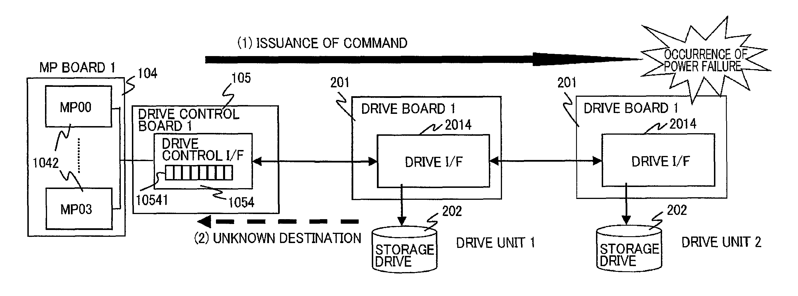
[0114]In contrast to the above typical conventional example, FIG. 15 shows an exemplary power failure detection system related to a configuration of Example 1 of the present embodiment. Unlike the configuration example in FIG. 13, MPs 1042 in charge of data I / O to and from storage drives 202 are mounted on each MP board 104, independently. In the example in FIG. 15, a MP board 104 is provided for each power supply system in a storage apparatus 10, and it is equipped with four MPs 1042. These MPs 1042 can communicate with any of the other MPs 1042 through the switch boards 102 shown in FIG. 4. In the present embodiment, at least one of the MPs 1042 is selected as a representative MP and is in charge of the processing for power supply monitoring and power failure detection, as will be described later.

[0115]A drive control board 105 does not include a circuit equivalent to the environment monitor control circuit 1055 in FIG. 13. The power supply information signal ...

example 2

in Present Embodiment

[0174]Next, description will be provided for a power failure detection system and its functions applied to a storage apparatus 10 in Example 2 of the present embodiment. FIG. 29 illustrates an exemplary power failure detection system according to Example 2. Since the overall configuration and component elements in FIG. 29 are almost the same as those in Example 1 shown in FIG. 15, the following explains different points from the configuration of Example 1.

[0175]In Example 1, the drive control I / F 1054 on the drive control board 105 in the controller device 100 is provided with the data data queue 10541 from which its stored data is deleted at the occurrence of a power failure, thereby to preferentially execute commands for processing of dealing with the power failure. A command deleted from the data queue 10541 at the occurrence of a failure, however, needs to be re-executed by each requester MP 1042 after the failure recovery, which produces a problem of increa...


PUM


Abstract

A storage apparatus has a physical storage area used by an external apparatus, a drive interface unit, a power supply unit, and a storage controller executing data write processing from the external apparatus to the storage drive and data read processing from the storage drive through the drive interface unit, and a drive control interface unit. The power supply unit inputs power supply information to the drive interface unit. Any one of the processing units acquires the power supply information of the power supply unit through a data network path to the drive interface unit for the data write processing and the data read processing, and determines whether or not a failure occurs in the power supply unit supplying the operation power to the storage drive and the drive interface unit, on the basis of the acquired power supply information.

Description

FIELD OF INVENTION[0001]The present invention relates to a storage apparatus and a method of detecting a power failure in a storage apparatus, and particularly relates to a storage apparatus and a method of detecting a power failure in a storage apparatus, which employ a more simplified hardware configuration and are capable of surely and quickly detecting and then dealing with a failure occurring in a power supply system of the storage apparatus.BACKGROUND ART[0002]A storage apparatus is an apparatus including a storage medium such as a hard disk drive (hereinafter, “HDD”) or a solid state drive (hereinafter, “SSD”) and providing a storage area for data to be processed by an application and other programs running on a host computer or the like, and is also referred to as a disk subsystem.[0003]In recent years, there has been an increasing demand that storage apparatuses should achieve further power saving, space saving, higher-density packaging, and cost down for manufacturing and ...

Claims


Application Information

Patent Timeline
Patent Type & Authority Patents(United States)
IPC IPC(8): G06F11/00
CPCG06F1/28
Inventor NAKAYAMA, YOSUKEINOUE, TETSUYAOGAWA, MASATOMIZUMURA, TAKAKATU
Owner HITACHI LTD
Why Eureka
Try Eureka