Ion Trap Mass Spectrometer

Active Publication Date: 2013-04-04
SHIMADZU CORP
View PDF10 Cites 6 Cited by
  • Summary
  • Abstract
  • Description
  • Claims
  • Application Information

AI Technical Summary

Benefits of technology

[0015]The present invention is made to solve the problems referred to above. The main purpose of the invention is, in the ion trap mass spectrometer using the DIT, to ensure that ions with a high mass-to-charge ratio are also trapped in the ion trap and to avoid losing the peak of a maximum mass-to-charge ratio on a mass

Problems solved by technology

If this gap becomes larger and, in particular, the mass-dependence becomes larger, it becomes more difficult to accurately trap the target ions with a desired mass-to-charge ra

Method used


Image

  • Ion Trap Mass Spectrometer
  • Ion Trap Mass Spectrometer
  • Ion Trap Mass Spectrometer

Examples


first embodiment

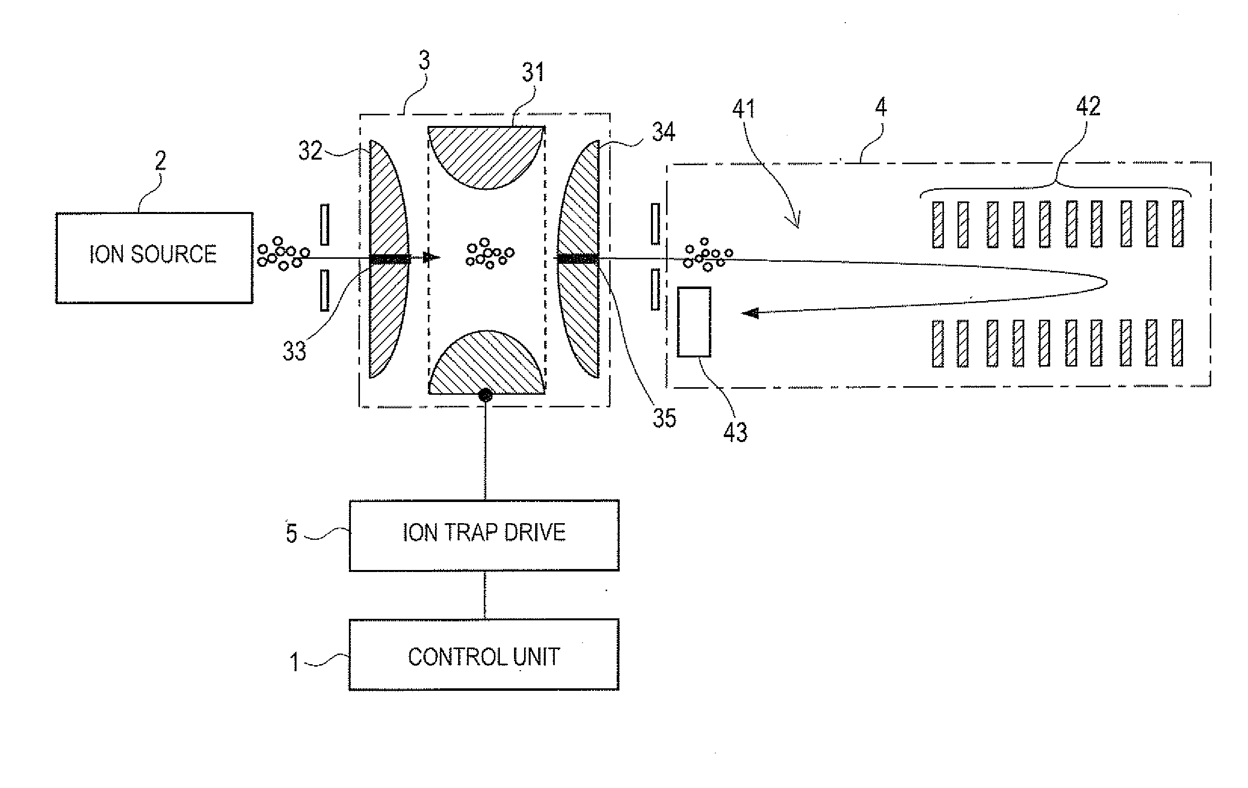
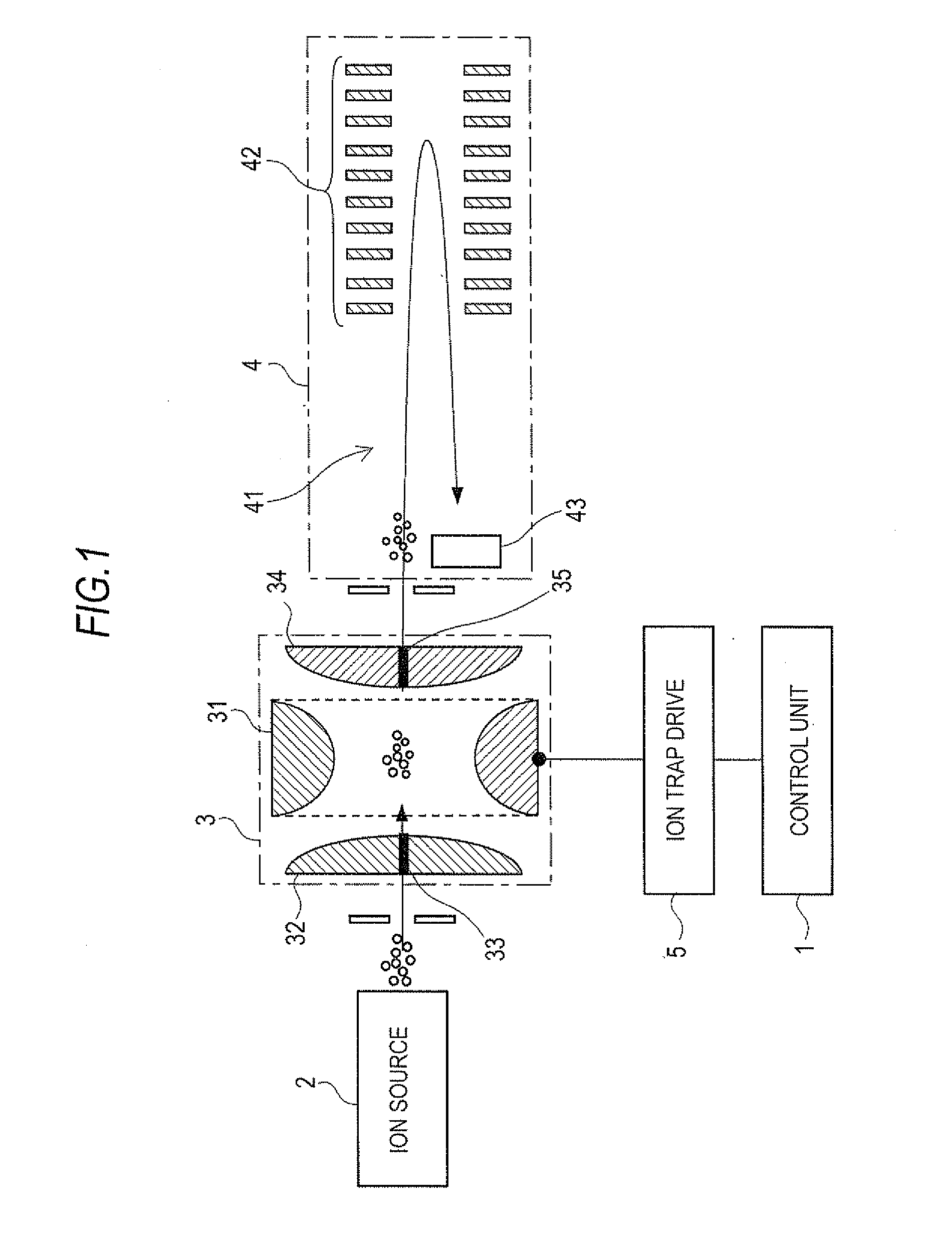
[0040]The DIT-TOFMS, one embodiment of the ion trap mass spectrometer according to the present invention, is described next with reference to the attached figures. FIG. 1 shows a schematic view of the configuration of the DIT-TOFMS of the

[0041]The DIT-TOFMS of the first embodiment comprises: the ion source 2 that ionizes target specimens; the 3D quadrupole ion trap 3 that temporarily holds ions and manipulates such ions in various ways, such as mass separation and collision-induced dissociation; and the time-of-flight mass spectrometer 4 that detects ions emitted from the ion trap 3 after mass-separation.

[0042]No particular ionization method is specified in the ion source 2. For liquid specimens, atmospheric pressure ionization methods such as the electrospray ionization (ESI) method and the atmospheric pressure chemical ionization (APCI) method are used. For solid specimens, methods such as the matrix-assisted laser desorption / ionization (MALDI) method are used.

[0043]As described a...

second embodiment

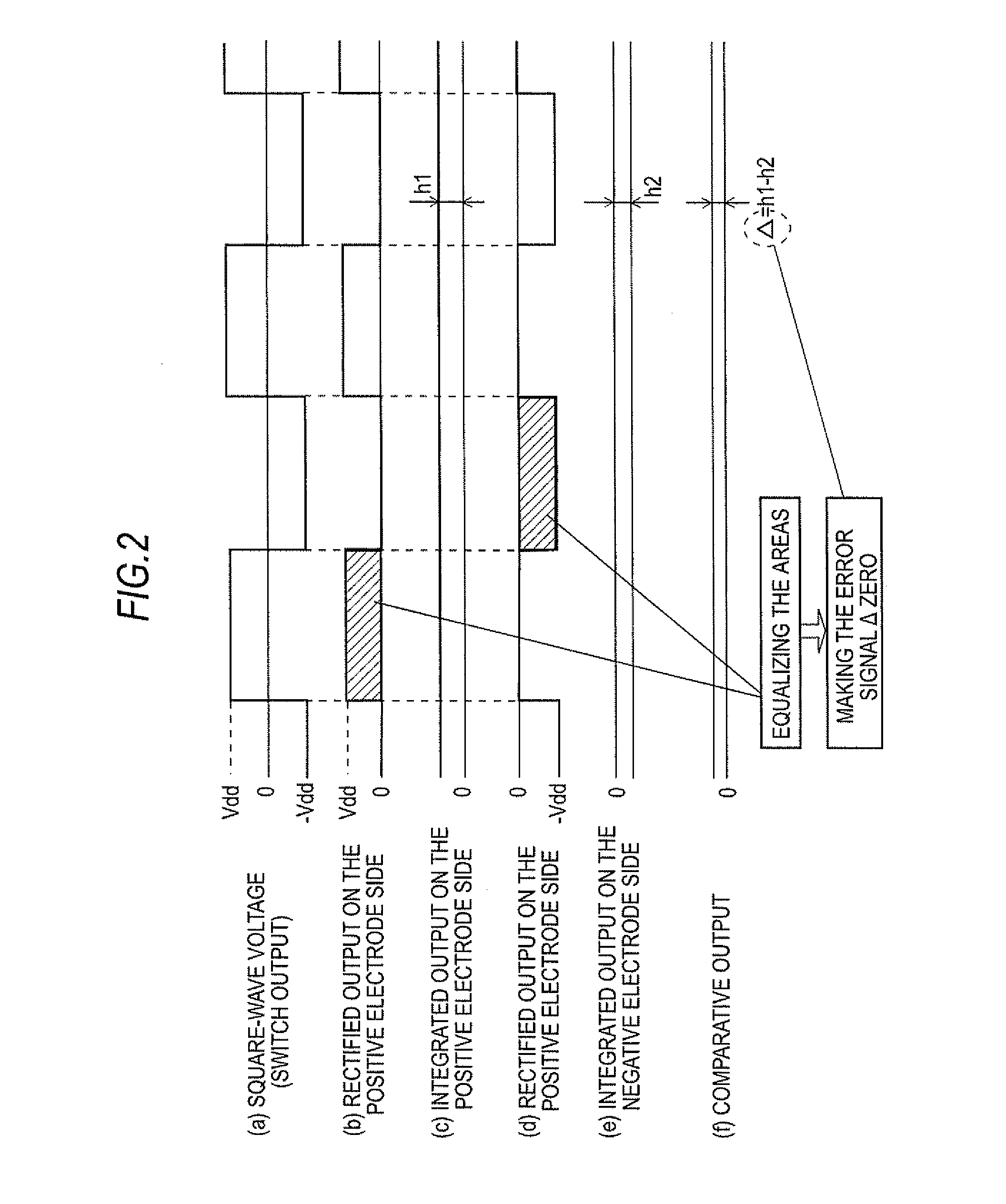
[0059]Accordingly, the output voltages from the positive electrode side variable high-voltage DC power supply 62 and the negative electrode side variable high-voltage DC power supply 63 are controlled by feedback so that they may achieve the respective set peak value. As described above, the duty ratio is controlled so that the areas of a square-wave voltage on the positive and negative electrode sides become identical under the condition that the absolute values of output voltages from the positive electrode side variable high-voltage DC power supply 62 and the negative electrode side variable high-voltage DC power supply 63 are identical and thus, the duty ratio is maintained at around 50%. In the configuration of the second embodiment, the duty ratio can be maintained at 50% with the peak values of square-wave voltages on the positive and negative electrode sides applied to a ring electrode being identical. This can improve the detection sensitivity in the high mass-to-charge rat...


PUM


Abstract

An ion trap mass spectrometer with high sensitivity for detection in the high mass-to-charge ratio is provided. with separate measurement of square-wave voltages on the positive and negative electrode sides applied to a ring electrode in rectifying circuits and smoothing the measured voltages in integrating circuits, respectively, the areas of square-wave voltages on the positive and negative electrode sides are replaced with the peak values h1 and h2 of DC signals, respectively. A comparator circuit outputs the difference of said peak values as the error signal Δ, and variable delay circuits adjust the amount of delay of control signals so that the error signal Δ becomes zero. This changes the relative phase relation between control signals on the positive and negative electrode sides that turn on and off the switches, and renders the duty ratio of square-wave voltages nearly 50%.

Description

TECHNICAL FIELD[0001]The present invention relates to an ion trap mass spectrometer with an ion trap that confines ions by the action of a high-frequency electric field and relates more specifically to an ion trap mass spectrometer using a digital-driven ion trap.BACKGROUND ART[0002]In an ion trap mass spectrometer, an ion trap is used to confine ions by the action of a high-frequency electric field to separate ions with a specific mass-to-charge ratio (m / z) and further to dissociate such separated ions. A typical ion trap is in 3D quadrupole configuration composed of one ring electrode the inside surface of which is a hyperboloid of revolution of one sheet and a pair of endcap electrodes the inside surface of which is a hyperboloid of revolution of two sheets that are disposed facing each other across said ring electrode. In addition, an ion trap in linear configuration composed of four rod electrodes disposed parallel to each other is also well-known. In this specification, for co...

Claims


Application Information

Patent Timeline
IPC IPC(8): H01J49/26
CPCH01J49/424
Inventor TANIGUCHI, JUNICHI
Owner SHIMADZU CORP
Why Eureka
Try Eureka