Blind spot display apparatus

Inactive Publication Date: 2013-03-12
PIECE FUTURE PTE LTD
View PDF20 Cites 10 Cited by
  • Summary
  • Abstract
  • Description
  • Claims
  • Application Information

AI Technical Summary

Benefits of technology

The present invention is about a blind spot display apparatus that can show an image of a blind spot at an intersection that cannot be seen from the driver's perspective. It uses omni-directional images generated by two image generating units to create a realistic display for the driver. This allows the driver to see the situation in the blind spot and detect danger more easily. The apparatus can also perform three-dimensional transformation to create a more precise view of the intersection blind spot. The technical effects of the invention include improved safety and awareness for drivers and reduced risk of accidents.

Problems solved by technology

However, since only the images in a direction of the driver's line of sight can be generated according to the method disclosed in Patent Reference 1, video of a blind spot caused by an intersection cannot be generated.
Even when the vehicle is equipped with the GPS receiver, the precision is low and the receiver cannot obtain height information.
Thus, there is a problem that the transformed video may become the one captured at a viewpoint far distant from the driver's viewpoint.
Furthermore, the method disclosed in Non-patent Reference 1 results in another problem that only an overhead view from above an intersection can be generated, and that it is difficult to make an intuitive determination from which direction a vehicle or a pedestrian enters the intersection at first glance of images from intersection information.

Method used


Image

  • Blind spot display apparatus
  • Blind spot display apparatus
  • Blind spot display apparatus

Examples


embodiment 1

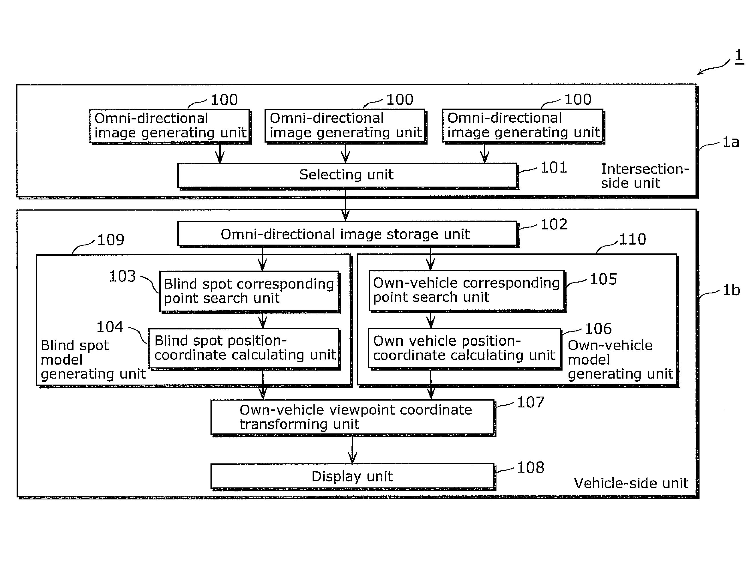
[0048]FIG. 1 is a block diagram illustrating a configuration of a blind spot display apparatus 1 according to Embodiment 1 in the present invention.

[0049]The blind spot display apparatus 1 includes an intersection-side unit 1a and a vehicle-side unit 1b. The vehicle-side unit 1b may be one of vehicle-side units 1b included in the blind spot display apparatuses 1 and installed in each vehicle. The blind spot display apparatus 1 includes: (i) the intersection-side unit 1a including a selecting unit 101 at an intersection where omni-directional image generating units 100 each of which obtains an omni-directional image are respectively placed on different three-dimensional position coordinates (see FIG. 3 and others); and (ii) the vehicle-side unit 1b including an omni-directional image storage unit 102, a blind spot corresponding point search unit 103, a blind spot position-coordinate calculating unit 104, an own-vehicle corresponding point search unit 105, an own vehicle position-coor...

embodiment 2

[0120]FIG. 13 is a block diagram illustrating a configuration of a blind spot display apparatus 1C according to Embodiment 2 in the present invention. The blind spot display apparatus 1C includes: an intersection-side unit 1Ca including a selecting unit 1001 at an intersection where omni-directional image generating units 100 each of which obtains an omni-directional image are respectively placed on different three-dimensional position coordinates; and each of the vehicle-side units 1Cb includes an omni-directional image storage unit 102, a blind spot corresponding point search unit 1003 including a left blind spot corresponding point search unit 1004 and a right blind spot corresponding point search unit 1005, a blind spot position-coordinate calculating unit 104, an own-vehicle corresponding point search unit 105, an own vehicle position-coordinate calculating unit 106, an own-vehicle viewpoint coordinate transforming unit 107, and a display unit 108. The omni-directional image ge...

embodiment 3

[0131]FIG. 15 illustrates a block diagram of a configuration of a blind spot display apparatus 1D according to Embodiment 3 of the present invention. The blind spot display apparatus 1D includes: an intersection-side unit 1Da including omni-directional image holding units 1201, omni-directional difference image generating units 1202, and a selecting unit 1203 at an intersection where omni-directional image generating units 100 each of which obtains an omni-directional image are respectively placed on different three-dimensional position coordinates; and each of vehicle-side units 1Db including an omni-directional image storage unit 102, a blind spot corresponding point search unit 1205 including a left blind spot corresponding point search unit 1206 and a right blind spot corresponding point search unit 1207, a blind spot position-coordinate calculating unit 104, an own-vehicle corresponding point search unit105, an own vehicle position-coordinate calculating unit 106, an own-vehicl...


PUM


Abstract

A blind spot display apparatus presents a situation at a blind spot occurring at an intersection from a driver's viewpoint, in a method of presenting the situation to a driver. The blind spot display apparatus includes: an omni-directional image storage unit storing omni-directional images obtained at different positions; a blind spot model generating unit calculating a position of the object based on each image of the object (in the blind spot) included in the omni-directional images; an own-vehicle model generating unit calculating a position of a vehicle based on images of the vehicle included in the omni-directional images; an own-vehicle viewpoint coordinate transforming unit transforming the calculated position of the object into display coordinates relative to the calculated position of the vehicle; and a display unit that performs display.

Description

TECHNICAL FIELD[0001]The present invention relates to an image processing apparatus with a technique that is a combination of a computer graphics technique and a technique using an image obtained from a camera, and in particular to an apparatus that displays, on a display, an image of a blind spot that is at an intersection and that cannot be seen from an own vehicle.BACKGROUND ART[0002]As one of the approaches of Intelligent Transport Systems (ITS) promoted by the Ministry of Land, Infrastructure, Transport and Tourism, services for drivers have been considered, such as alerting a driver currently driving a vehicle and providing alert support. In particular, the collision prevention support service will be an important approach to prevent accidents at an intersection where head-on accidents frequently occur. Currently, informing a driver of a situation at an intersection to be a blind spot for the driver using road sensors and image sensors are under review. Furthermore, the image ...

Claims


Application Information

Patent Timeline
IPC IPC(8): B60Q1/00G06T19/00
CPCG08G1/16H04N5/2259H04N5/2628G08G1/166G08G1/167H04N23/58
Inventor YUDA, MASATO
Owner PIECE FUTURE PTE LTD
Why Eureka
Try Eureka