Aviation emergency response system

a technology for emergency response and aviation, applied in the field of emergency response systems for aviation disasters, can solve the problems of aviation accidents that tend to be considerably more catastrophic, no transportation system is perfectly safe, and the chance of an accident, so as to increase the safety of aircra

Inactive Publication Date: 2013-03-12
ALABDEEN ADEL JUMAH
View PDF9 Cites 4 Cited by
  • Summary
  • Abstract
  • Description
  • Claims
  • Application Information

AI Technical Summary

Benefits of technology

[0009]The aviation emergency response system comprises a number of different ground-based and aircraft-based subsystems that each provide an increase in safety for aircraft. Many of the systems interface with one another to provide authorities with accurate information as to the nature of an emergency or problem, and to enable those authorities to make the proper response.
[0010]One such subsystem comprises a plurality of retractable, remotely controlled fluid dispensers disposed along the edges of a runway for dispensing water, fire retardant foam, and/or deicing chemicals on the runway when required. A plurality of cameras may also be provided along the sides of the runway to enable authorities to accurately direct any response to an emergency that may occur on the runway. The runway may also include electrically resistant heating elements therein to melt ice, and/or devices to puncture the tires of an aircraft should such action become necessary. The runway preferably includes an energy-absorbent overrun area at each end. Appropriate dams or berms along the edges of the runway may also be provided for the retention of beneficial liquids thereon, and/or the runway may include appropria

Problems solved by technology

It is an unfortunate fact that no transportation system is perfectly safe.
Anytime there is moving machinery, there is some chance for an accident.
Generally speaking, aviation accidents tend to be considerably more catastrophic than other transportation accidents due to the large number of passengers carried on larger airline aircraft, and also due to the speed at which such aircraft fly.
Nevertheless, the occasional airline accident sti

Method used


Image

  • Aviation emergency response system
  • Aviation emergency response system
  • Aviation emergency response system

Examples


Embodiment Construction

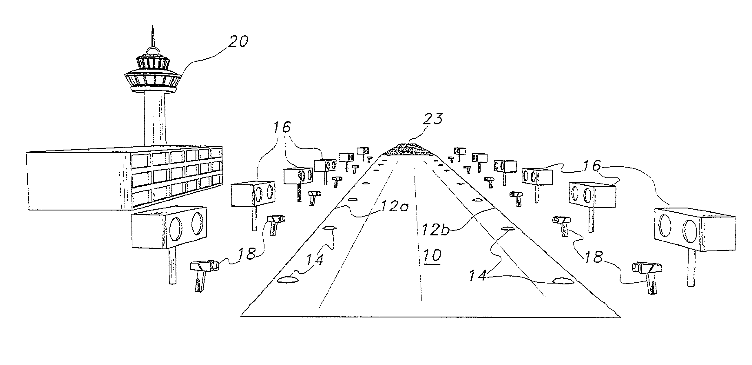
[0021]The aviation emergency response system comprises multiple ground-based and aircraft-based subsystems serving to increase aviation safety and / or to reduce the severity of aircraft accidents or incidents. The various subsystems communicate with a control facility or station that, in turn, monitors the subsystems. Personnel in the control station respond with appropriate actions as required to meet an emergency situation as it arises and develops. The aircraft-based subsystems also communicate with the ground-based control station, and also with a cockpit annunciator and monitor.

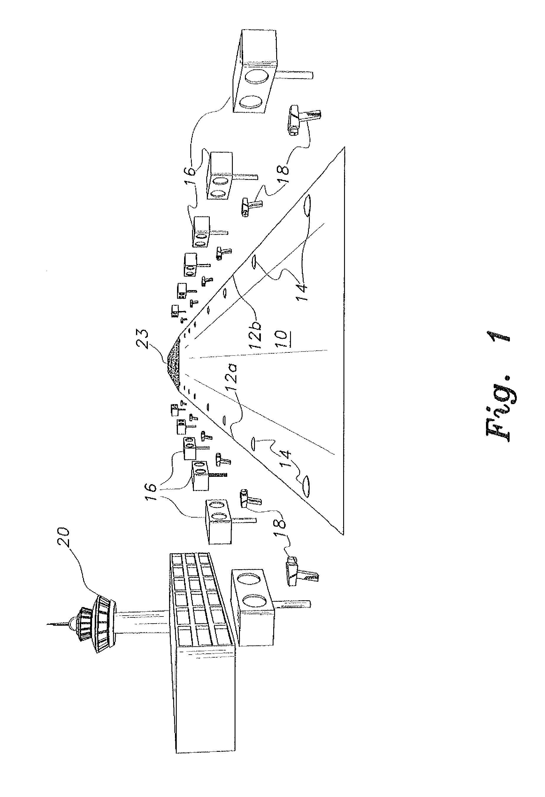
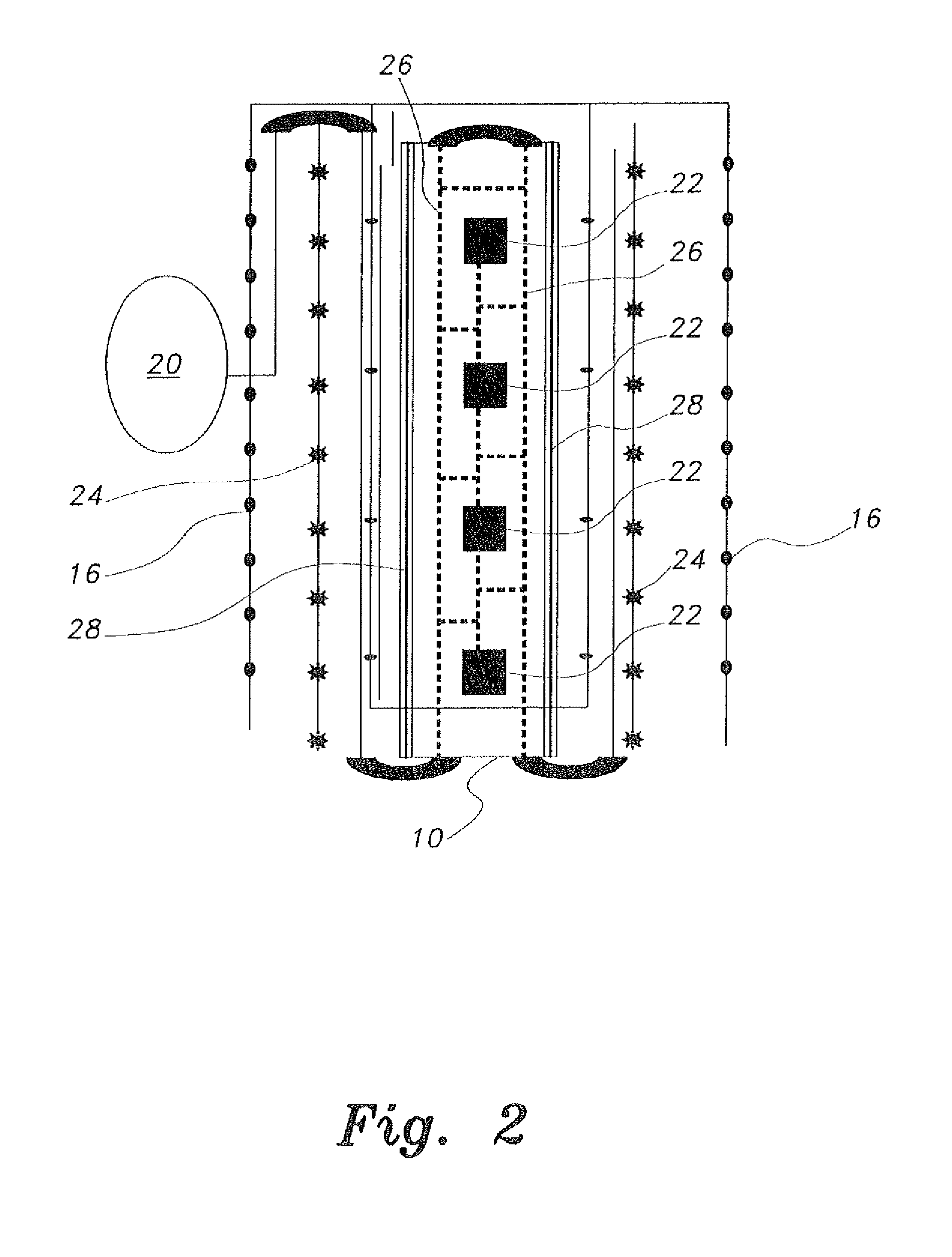
[0022]FIG. 1 of the drawings provides a perspective view of an exemplary airport runway 10 equipped with a number of the subsystems of the aviation emergency response system. FIG. 2 provides a schematic plan view of the runway 10 of FIG. 1. The runway 10 includes mutually opposed lateral edges 12a and 12b. Each edge 12a, 12b has a plurality of runway monitoring cameras 14 embedded in the runway adjacent t...


PUM


Abstract

The aviation emergency response system includes a number of ground subsystems located on an airport, and a number of subsystems installed in an aircraft. The ground subsystems may include dispensers along the edges of the runway(s) for dispensing foam, water, and/or deicing fluid, and an array of cameras installed along the runway edges. Low lateral retaining dams may be provided along the edges of the runway(s), and appropriate drainage is also provided for the runway. A tire-puncturing apparatus may also be installed in the surface of the runway, and energy-absorbing overruns are provided at the runway ends. A control center including appropriate monitoring and control systems is also provided on the airport. Aircraft may be equipped with external cameras for monitoring the condition of the aircraft in flight, and corresponding annunciator systems placed in the aircraft cockpit for appropriate response(s) by the flight crew.

Description

CROSS-REFERENCE TO RELATED APPLICATIONS[0001]This is a continuation of my prior application Ser. No. 12 / 311,455, filed Dec. 5, 2011 now pending.BACKGROUND OF THE INVENTION[0002]1. Field of the Invention[0003]The present invention relates to systems for handling aviation disasters, and particularly to an aviation emergency response system for aircraft in distress.[0004]2. Description of the Related Art[0005]It is an unfortunate fact that no transportation system is perfectly safe. Anytime there is moving machinery, there is some chance for an accident. Transportation accidents receive the greatest notice in the field of aviation, partly because such accidents have become relatively uncommon due to the significant advances in safety that have been developed over the years. Another reason for the attention that aviation accidents receive is their relative severity. Generally speaking, aviation accidents tend to be considerably more catastrophic than other transportation accidents due t...

Claims


Application Information

Patent Timeline
IPC IPC(8): G09B9/00
CPCB64F1/36G08G5/0004G09B9/00B64F1/02B64F1/0299
Inventor ALABDEEN, ADEL JUMAH
Owner ALABDEEN ADEL JUMAH
Why Eureka
Try Eureka