

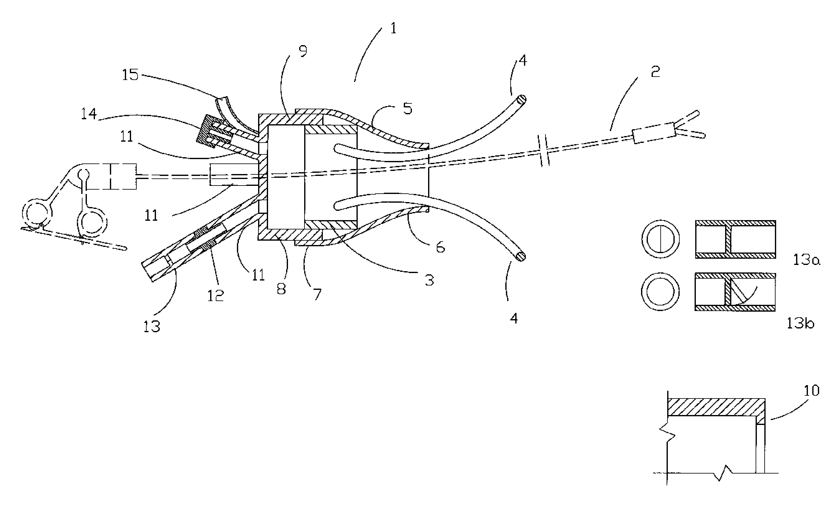
Surgical instrument equipment appropriate for mini-invasive surgery
a surgical instrument and mini-invasive technology, applied in the field of surgical instrument equipment, can solve the problems that the surgeons who perform minimally invasive surgery have to learn more difficult surgical techniques, and achieve the effect of improving surgical accuracy and accuracy
- Summary
- Abstract
- Description
- Claims
- Application Information
AI Technical Summary
Benefits of technology
Problems solved by technology
Method used
Image

Examples
first embodiment
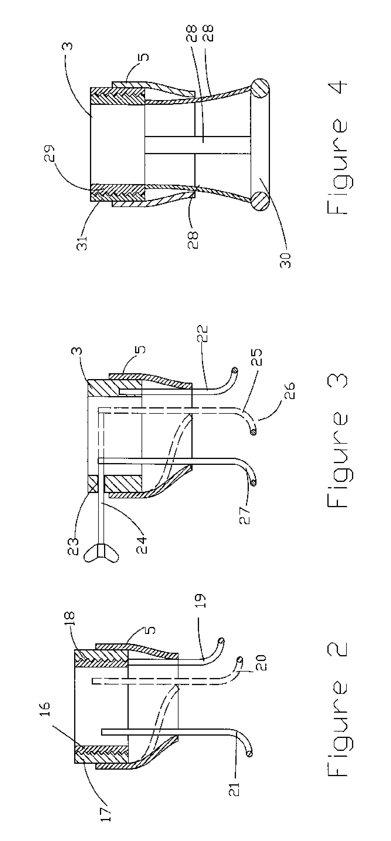
[0030]In FIG. 2, the invention is shown, wherein the rigid ring is made up by two concentric pieces (16; 17), both joined to each other by means of a thread (18). The external piece (17) shows an inner thread and has a first separator (19) firmly fixed to its external surface and it is the piece that holds the flexible multivalve head when in use. The inner piece (16) shows an external thread and has a second separator (20) firmly fixed to its inner surface. When using surgical instruments, both separators are coincidentally located on a same radius and the flexible funnel (5) is mounted on both separators (this embodiment is illustrated in FIG. 2 with dotted lines). When both concentric pieces are rotated, separators get apart up to a desired position, preferably one diametrically opposed to the other, and the flexible funnel acquires the new shape adopted by said separators in their new position: the steady separator (19) and the new position of the second separator (20) (this emb...
second embodiment
[0031]In FIG. 3, the invention is seen, wherein the rigid ring (3) shows a steady separator (22) on its inner side and, on the opposite side of said steady separator, a threaded hole (23) is provided, within which a screw (24) rotates. The inner end of said screw is joined to a movable separator (25) and in its external end an element known in the art is provided to tighten / release said screw. The displacement the screw performs with respect to the rigid ring radially moves the movable separator. To use this embodiment, both separators are closely placed (initial layout (26) of movable separator illustrated in FIG. 3 with dotted line), the flexible funnel (5) is placed on said separators and the rigid ring and subsequently the movable separator is displaced by means of the screw. The funnel will follow the movable separator up to its operative position (27).
[0032]In all these embodiments, separators are made of a thin element, elongated in “U” shape, whether rigid, flexible or a com...
third embodiment
[0035]In FIG. 4, the invention is shown, wherein separators are retracting straps or ropes (28), preferably of elastic material, joined on one end to a rigid head holder ring (29) and on the other to an elastic ring (30) which shape can be modified (get deformed.). A retracting rigid ring (31) provides an external thread in which the rigid head holder ring fits, both working in conjunction. By using this embodiment, the modified (deformed) elastic ring is inserted with the straps together with the funnel (5) by the wall of the patient's cavity; once this set is inserted, the flexible ring goes back to its original shape and both rigid rings get locked, the retractring and the head holder rings. By rotating the retracting ring, the rigid head holder ring is moved away from the patient, dragging the flexible ring against the patient's opening and against the retracting ring, the straps get tight and rigidly enough so as to bear the pressure of entering the patient's cavity through the...
PUM
 Abstract
Description
Claims
Application Information