Offset cup impactor with an expandable dome for double mobility implants

a double-movement, impactor technology, applied in the field of surgical inserters, can solve the problems of difficult cleaning, difficult control, and difficult cleaning of complicated mechanical devices, and achieve the effect of facilitating the sterilization of instruments and cleaning

a double-movement, impactor technology, applied in the field of surgical inserters, can solve the problems of difficult cleaning, difficult control, and difficult cleaning of complicated mechanical devices, and achieve the effect of facilitating the sterilization of instruments and cleaning

US8398650B1Active Publication Date: 2013-03-19VIANT AS&O HLDG LLC

Image

  • Offset cup impactor with an expandable dome for double mobility implants
  • Offset cup impactor with an expandable dome for double mobility implants
  • Offset cup impactor with an expandable dome for double mobility implants

Examples


Embodiment Construction

)

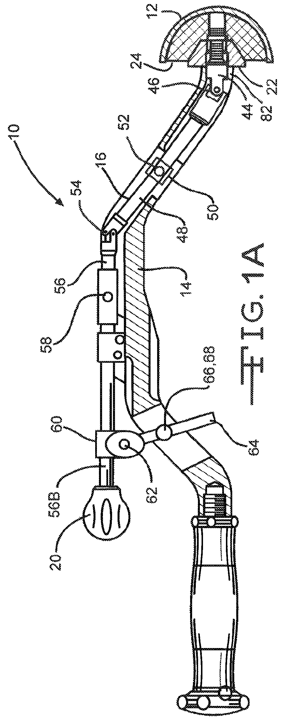
[0024]Referring now to FIGS. 1A-1C, an acetabular inserter 10 is provided to aid the surgeon in controlling the installation of an acetabular cup prosthesis 12. The inserter 10 has a housing 14 which encloses a drive train 16 having, at a distal end, a prosthesis engaging subassembly 18, and at the proximal end, a handle 20 which facilitates moving of the drive train by the operator. The housing 14 may be C-shaped, as shown, in order to minimize the invasiveness of the surgery by better clearing anatomical structures and tissue.

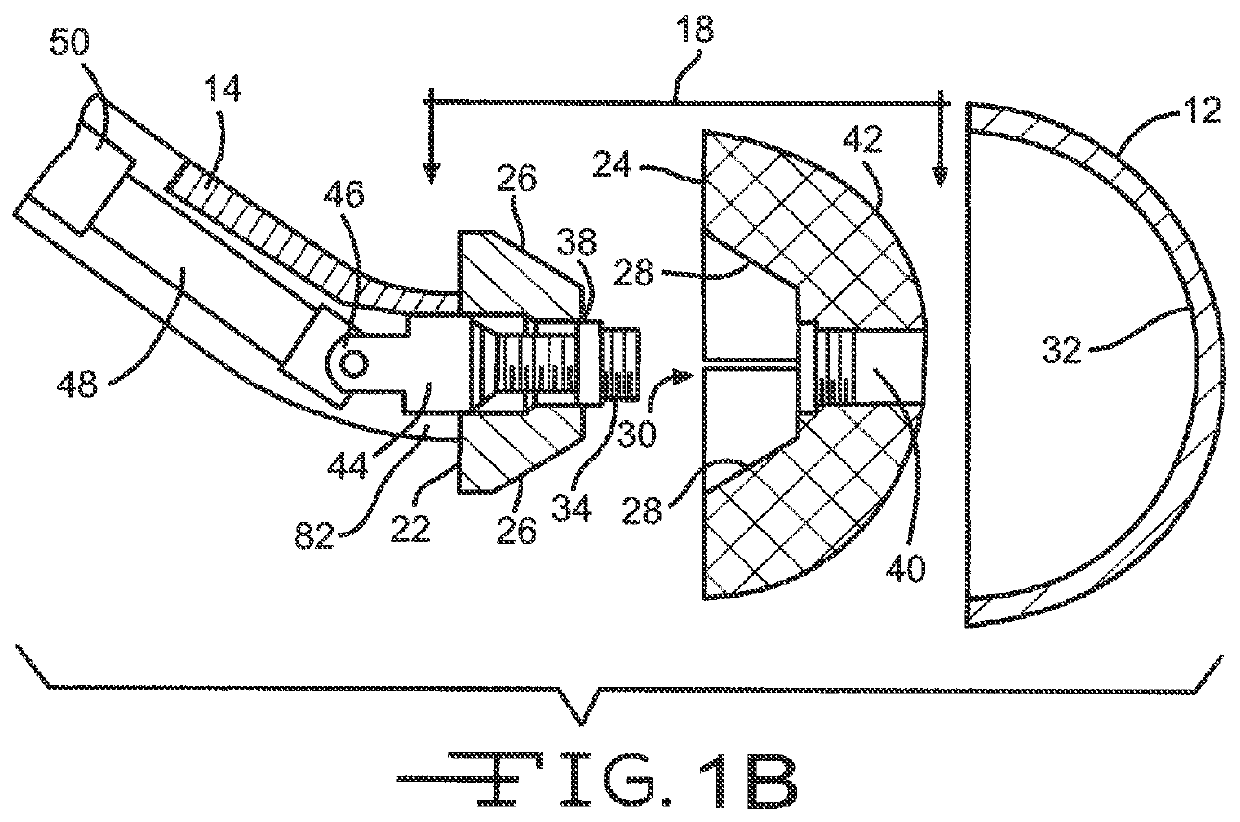
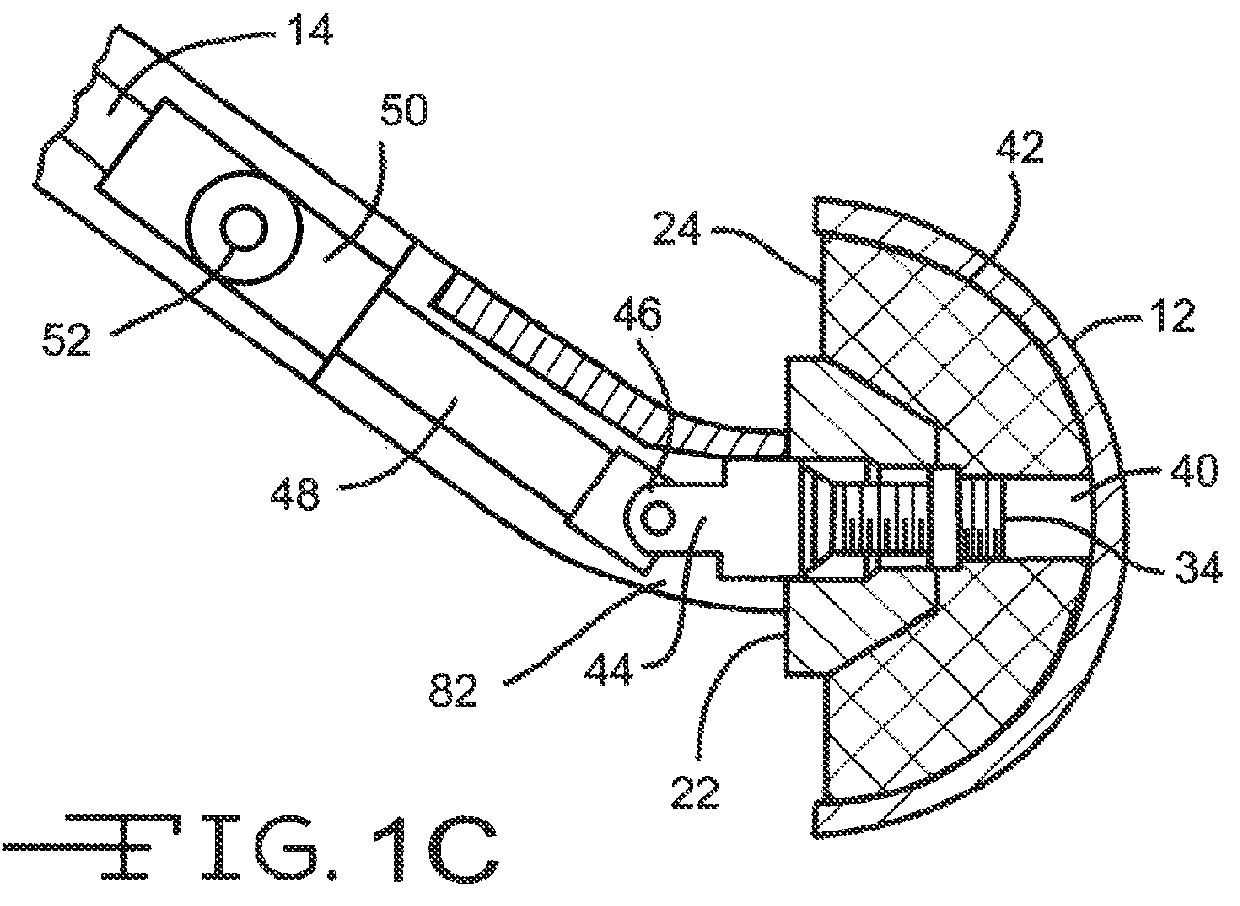
[0025]The subassembly 18 comprises a nose 22 and a dome 24 that are in direct communication with each other. The dome 24 is designed to expand into the double mobility acetabular cup prosthesis 12 to provide a substantially friction tight engagement which enables precise control of the prosthesis 12 during implantation in the body.

[0026]The distal end of the nose 22 has a frustro-conical shape that engages the dome 24 in its proximal end. The nose 22 has an ...


PUM


Abstract

An orthopaedic prosthetic inserter used for the implantation of double mobility implants is described. The inserter consists of a drive train, a C-shaped housing, and a prosthetic cup grabbing subassembly. The subassembly comprises a frustro-conical nose and an expandable dome. When activated by the drive train, the dome expands into the cup of the prosthetic to manipulate the prosthetic during implantation.

Description

CROSS REFERENCE TO RELATED APPLICATIONS[0001]This application claims priority to U.S. provisional application Ser. No. 61 / 147,504, filed on Jan. 27, 2009.BACKGROUND OF THE INVENTION[0002]This invention relates to surgical inserters for aiding in installing orthopedic prostheses, and more specifically, to easily sterilizable inserters for installing acetabular implants in the acetabular socket.[0003]A double mobility prosthetic cup is a type of acetabular implant that is designed to increase a patient's range of mobility. Unlike other types of actabular implants, double mobility prosthetic cups do not have an opening through the cup portion which allows for easy manipulation during implantation. For example, a rod is typically threaded through the cup opening. This rod is used like a handle with which to control and guide the implant during implantation. Double mobility implants, on the other hand, do not have such an opening and therefore create a challenge in controlling them durin...

Claims


Application Information

Patent Timeline
19 Mar 2013
Publication
US8398650B1
IPC
A61B17/58
CPC
A61F2/4609; A61F2002/30579; A61F2002/30591; A61F2002/3208; A61F2002/4627; A61F2002/30589
Inventors
BURGI, JONAS