
Operation assisting system

a technology of assisting system and assisting arm, which is applied in the field of operation assisting system, can solve the problems of extraordinary cost as required for installing and operating this system, and the deterioration of the accuracy of positional detection, and achieve the effect of accurate detection of the inclination of the pelvis

Inactive Publication Date: 2013-03-19
SAGA UNIVERSITY
View PDF19 Cites 43 Cited by
  • Summary
  • Abstract
  • Description
  • Claims
  • Application Information

AI Technical Summary

Benefits of technology

The system ensures high accuracy and operability during hip replacement surgeries by providing real-time deviation guidance, reducing the risk of bone dislocation and improving post-operative joint function, while minimizing costs by eliminating the need for complex optical measurement systems.

Problems solved by technology

However, use of material such as the infrared markers, which require an optical detection, it is necessary to provide, in addition to the markers provided on the surface of the body of the patient and on the operation instrument, a positional measurement device to acquire optically the positions of the markers in an operation room, thus causing a problem of extraordinary costs as required for installing and operating this system.
A certain place at which the operator or assistant operates may disable the positional measurement device from directly monitoring the markers during the operation, with the result that the positions of the markers may not be acquired accurately, thus deteriorating accuracy of positional detection.

Method used


Image

  • Operation assisting system
  • Operation assisting system
  • Operation assisting system

Examples


first embodiment

[First Embodiment of the Present Invention]

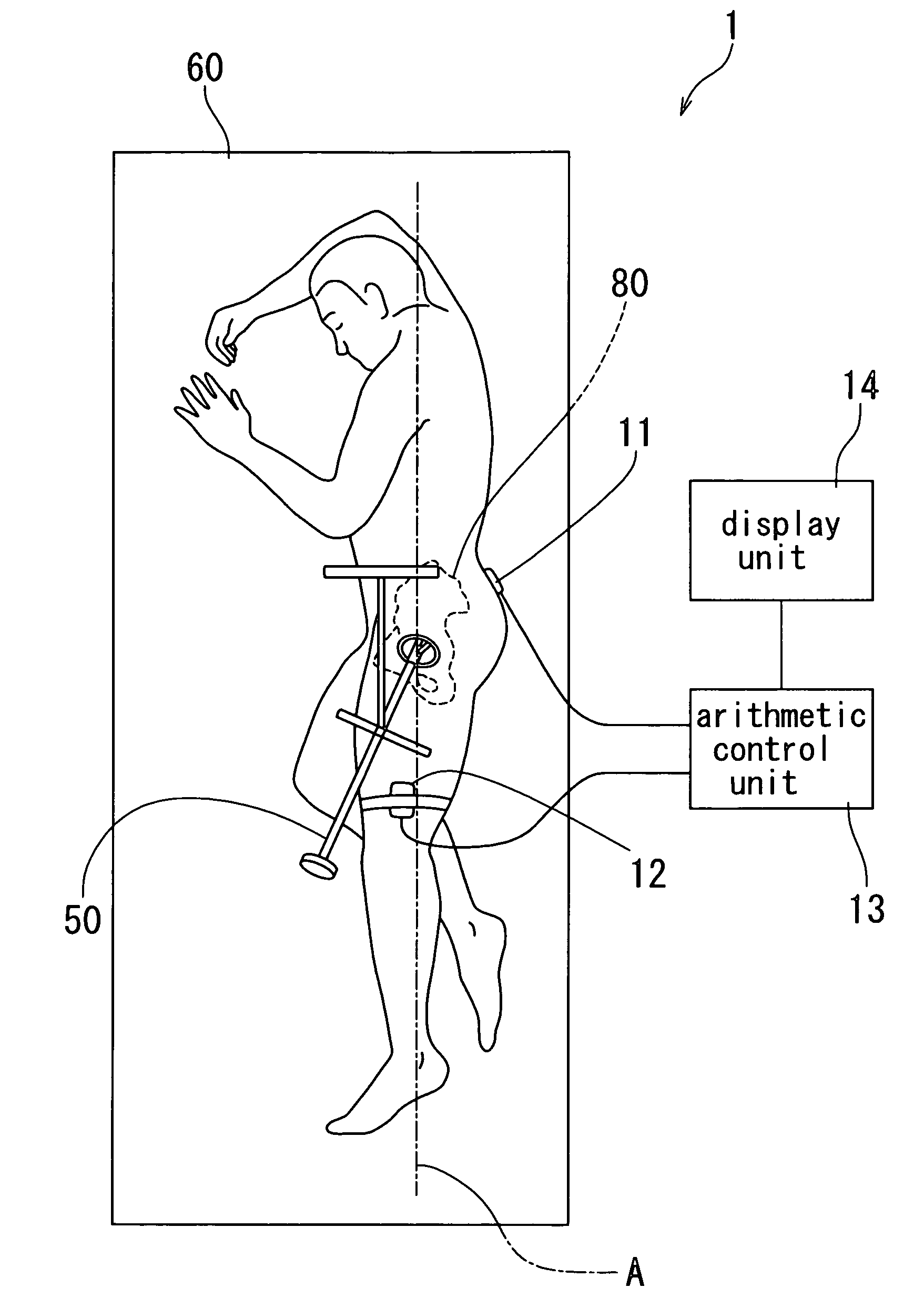
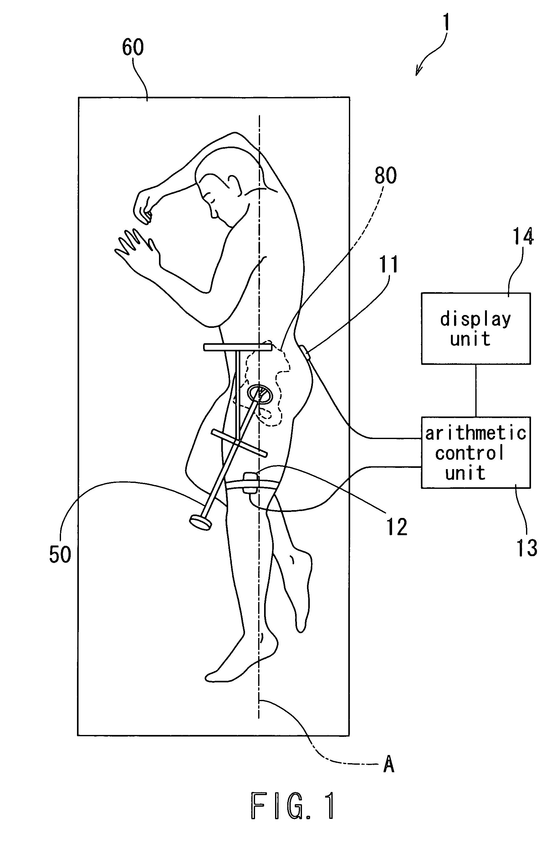
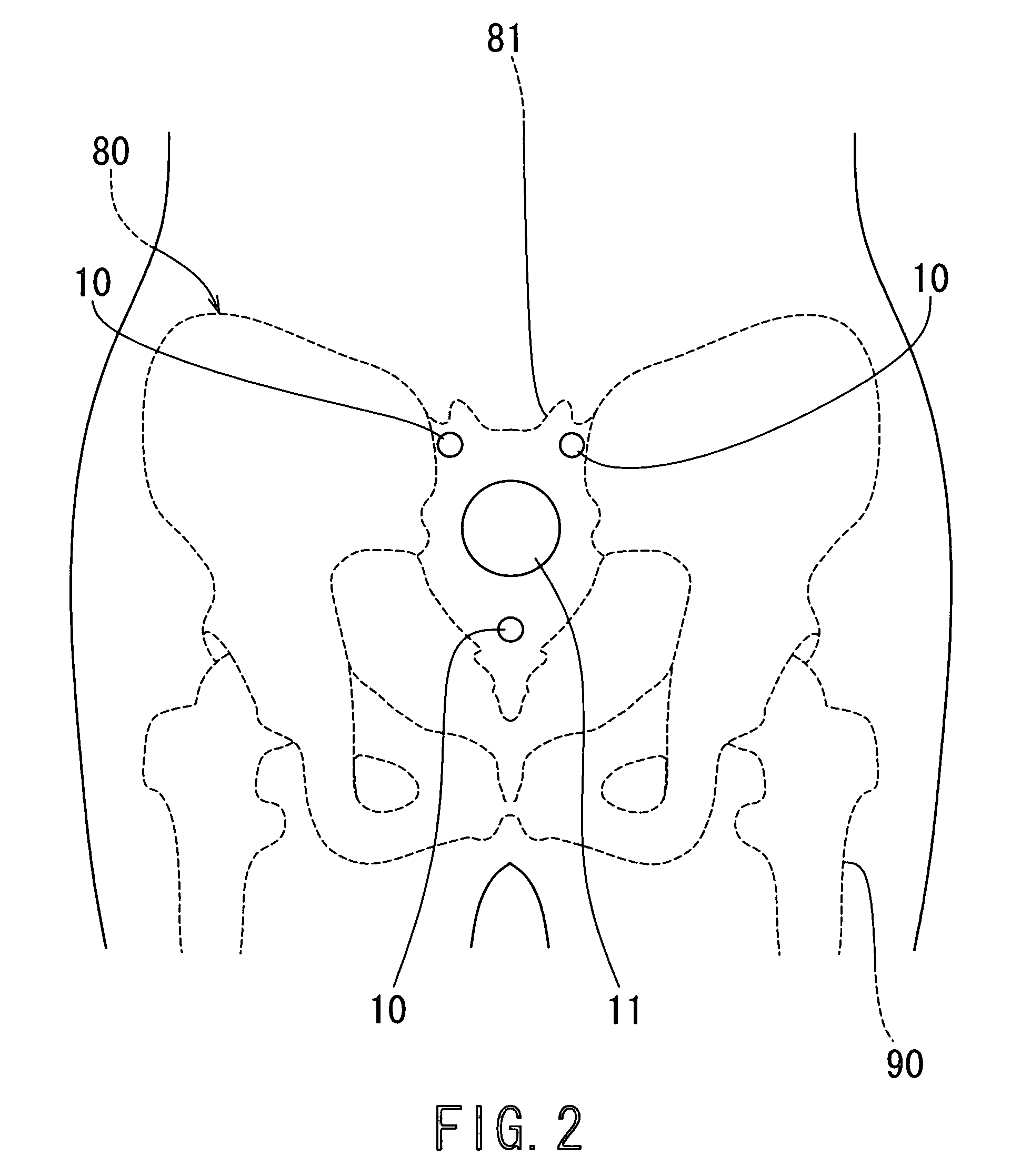
[0046]Now, an operation assisting system according to the first embodiment of the present invention will be described in detail below with reference to FIGS. 1 to 4.

[0047]In these respective figures, the operation assisting system 1 according to the first embodiment of the present invention comprises: three markers 10 that are provided on a surface of a body of a patient on a back side of a loin thereof, who is held in the decubitus position on an operation table 60, which is stationarily fixed during the operation, and have respective constant positional relationships; the first sensor 11 that is provided on the surface of the body of the patient so as to have constant positional relationship to the respective markers 10, to detect inclination of the first sensor 11 relative to a predetermined reference plane “A”; the third sensor 12 provided on the surface of the body of the patient at the femur region thereof to detect inclination of the...

second embodiment

[Second Embodiment of the Present Invention]

[0067]Now, the operation assisting system according to the second embodiment of the present invention will be described in detail below with reference to FIGS. 5 to 7.

[0068]In these respective figures, the operation assisting system 2 according to the second embodiment of the present invention comprises, three markers 20, the first sensor 21, the third sensor 23, the arithmetic control unit 24, and the display unit 14 in the same manner as the first embodiment as described above of the present invention, and further comprises, unlike the first embodiment of the present invention, the second sensor 22 provided on the operation instrument at a predetermined position thereof to detect at least inclination of the operation instrument 50 relative to the reference plane “A” (i.e., the plane extending perpendicularly to the upper surface of the operation table and in parallel with the longitudinal direction of the operation table).

[0069]The secon...


PUM


Abstract

An operation assisting system. When an operator manipulates an operation instrument to perform an operation for a joint surgery including a hip replacement, the operation assisting system provides the operator with information on the orientation of a bone such as a pelvis and an appropriate direction of the operation instrument relative to the bone to assist the operator so as to complete the operation in an easy and accurate manner, which ensures a high degree of operation accuracy and reduces the cost of the system.

Description

TECHNICAL FIELD[0001]The present invention relates to an operation assisting system, which permits to provide, when an operator manipulates an operation instrument to perform an operation for a joint surgery including a hip replacement, the operator with information on orientation of a bone such as a pelvis and an appropriate direction of the operation instrument relative to the bone to assist the operator so as to complete the operation in an easy and accurate manner, and particularly to such an operation assisting system, which permits to ensure a high degree of operation accuracy and reduce costs of the system.BACKGROUND OF THE INVENTION[0002]In a hip replacement coping with a hip osteoarthritis, parts for forming a prosthetic joint are substituted for a caput femoris and an acetabuli of a pelvis, respectively. An operation for the hip osteoarthritis includes removing partially the caput femoris and the acetabuli, and then implanting the parts substituting for the removed portion...

Claims


Application Information

Patent Timeline
Patent Type & Authority Patents(United States)
IPC IPC(8): A61F2/32A61F2/30A61F2/36A61B5/05A61B5/103G08B23/00G08B1/08
CPCA61B5/06A61B5/4528A61B17/1742A61B19/52A61B19/5244A61B5/4504A61B19/54A61B19/56A61B2019/507A61B2019/508A61B2019/5238A61B2019/5248A61B2019/5274A61B2019/5291A61B2019/5483A61F2/32A61F2/4609A61F2002/4632A61B2090/3983A61B90/36A61B2034/2048A61B2034/2074A61B34/20A61B34/25A61B2090/376A61B2034/107A61B2034/108A61B2090/365A61B90/39
Inventor HOTOKEBUCHI, TAKAOTERAMOTO, KENBUSHIGEMATSU, MASAMORI
Owner SAGA UNIVERSITY
Learn More