Radar echo processing with partitioned de-ramp

Active Publication Date: 2013-03-19
NAT TECH & ENG SOLUTIONS OF SANDIA LLC
View PDF7 Cites 24 Cited by
  • Summary
  • Abstract
  • Description
  • Claims
  • Application Information

AI Technical Summary

Problems solved by technology

It is well known that pure sinusoids combined with ADC nonlinearities (e.g., Integral Non-Linearity or INL) result in undesired spurious signals with maximum peak spectral amplitude.
In SAR systems, the result is false targets in the range/Doppler imagery.
In MTI systems, the result is false detect

Method used


Image

  • Radar echo processing with partitioned de-ramp
  • Radar echo processing with partitioned de-ramp
  • Radar echo processing with partitioned de-ramp

Examples


Embodiment Construction

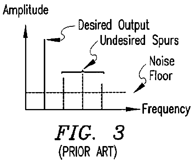
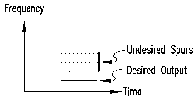
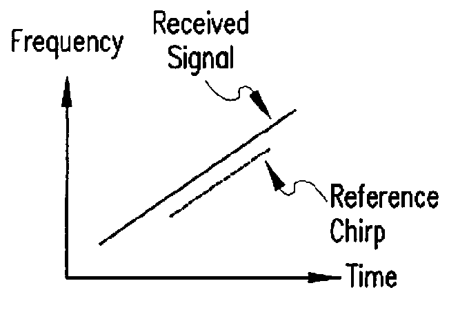
[0013]Exemplary embodiments of the present work modify the nature of the signal produced by a point-target, such that the signal deviates from a single-frequency tone, which in turn reduces the peak spurious amplitude in the data product. This is accomplished in some embodiments by apportioning the de-ramp operation across analog and digital processing domains. The reference chirp is selected to exhibit a slightly different frequency-vs.-time slope than that of the radar echo signal returned from the target. This results in a “partial” de-ramping operation in the analog processing domain, which produces a residual chirp at the ADC input. The residual chirp prevents point target signals from compressing to single-tone sinusoids at the ADC input. The residual chirp is ultimately removed by a de-ramp process in the digital processing domain, which recovers the single-tone representation of the point target signal. Although the desired output signal does “compress” to a sinusoid after t...


PUM


Abstract

The spurious-free dynamic range of a wideband radar system is increased by apportioning de-ramp processing across analog and digital processing domains. A chirp rate offset is applied between the received waveform and the reference waveform that is used for downconversion to the intermediate frequency (IF) range. The chirp rate offset results in a residual chirp in the IF signal prior to digitization. After digitization, the residual IF chirp is removed with digital signal processing.

Description

[0001]This application claims the priority under 35 U.S.C. §119(e)(1) of co-pending provisional application Ser. No. 61 / 352,853 filed Jun. 9, 2010 and incorporated herein by reference.[0002]This invention was developed under Contract DE-AC04-94AL85000 between Sandia Corporation and the U.S. Department of Energy. The U.S. Government has certain rights in this invention.FIELD OF THE INVENTION[0003]The present work relates generally to radar signal processing and, more particularly, to de-ramp processing of radar echo signals.BACKGROUND OF THE INVENTION[0004]De-ramp or “stretch” processing is commonly used in high-performance, wide-bandwidth radar systems to obtain fine range resolution without requiring unreasonably high or unobtainable Analog to Digital Converter (ADC) sampling frequencies and the resulting data processing burden. Systems that employ linear-FM “chirp” waveforms typically employ pulse compression by de-ramping, which mixes (convolves) the received signal (radar echo) ...

Claims


Application Information

Patent Timeline
IPC IPC(8): G01S13/58
CPCG01S7/32G01S13/282
Inventor DUBBERT, DALE F.TISE, BERTICE L.
Owner NAT TECH & ENG SOLUTIONS OF SANDIA LLC
Why Eureka
Try Eureka