
Liquid crystal display device capable of realizing both a wide viewing angle and a narrow viewing angle

a liquid crystal display and wide viewing angle technology, applied in static indicating devices, instruments, non-linear optics, etc., can solve the problems of wide viewing angle and the risk of allowing a person other than the user to see the secret document, and achieve the effect of wide viewing angl

Active Publication Date: 2013-03-19
LG DISPLAY CO LTD
View PDF4 Cites 15 Cited by
  • Summary
  • Abstract
  • Description
  • Claims
  • Application Information

AI Technical Summary

Benefits of technology

[0016]An advantage of the present invention is to provide a liquid crystal display device capable of realizing both a wide viewing angle and a narrow viewing angle according to a variety of uses thereof.
[0017]Additional advantages and features of the invention will be set forth in part in the description which follows and will become apparent to those having ordinary skill in the art upon examination of the following or may be learned from practice of the invention. These and other advantages of the invention may be realized and attained by the structure particularly pointed out in the written description and claims hereof as well as the appended drawings.
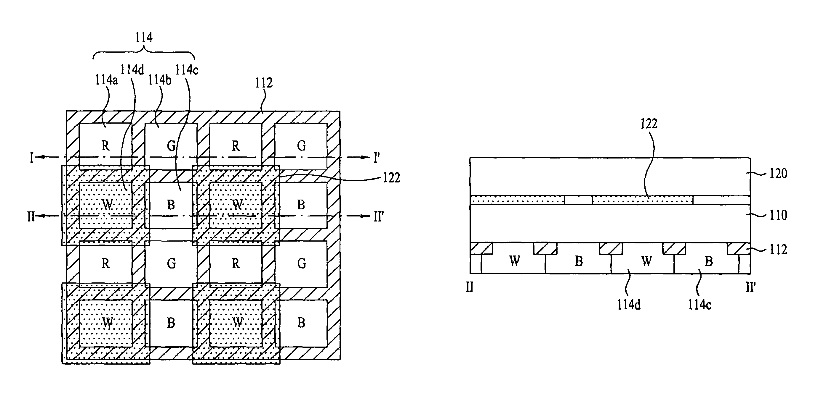
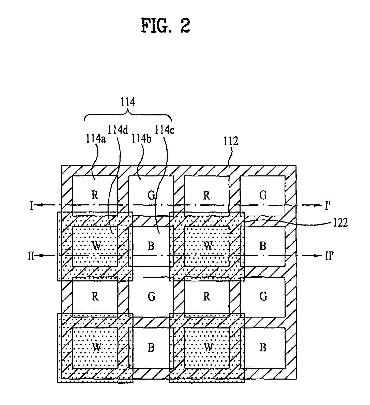
[0018]To achieve these and other advantages and in accordance with the purpose of the invention, as embodied and broadly described herein, a liquid crystal display device, in which a plurality of pixels are defined in a matrix form and each pixel includes red, green, blue, and white sub-pixels adjacent to one another vertically and horizontally, comprises: first, second, and third substrates sequentially stacked from the bottom; a thin-film transistor array formed on the first substrate; a black matrix formed on the second substrate between the first substrate and the second substrate at the boundary of the respective sub-pixels; color filter layers formed on the second substrate between the first substrate and the second substrate at the respective sub-pixels; and a barrier layer formed on the third substrate over each white sub-pixel, wherein an opening in the white sub-pixel has a smaller size than that of openings in the red, green, and blue sub-pixels, and an angle defined between a normal line of the second substrate and a line that connects an edge of the barrier layer with an edge of the black matrix formed below the barrier layer is larger than a value calculated by subtracting 5 degrees from an angle causing the total reflection of light to be passed through the second substrate.

Problems solved by technology

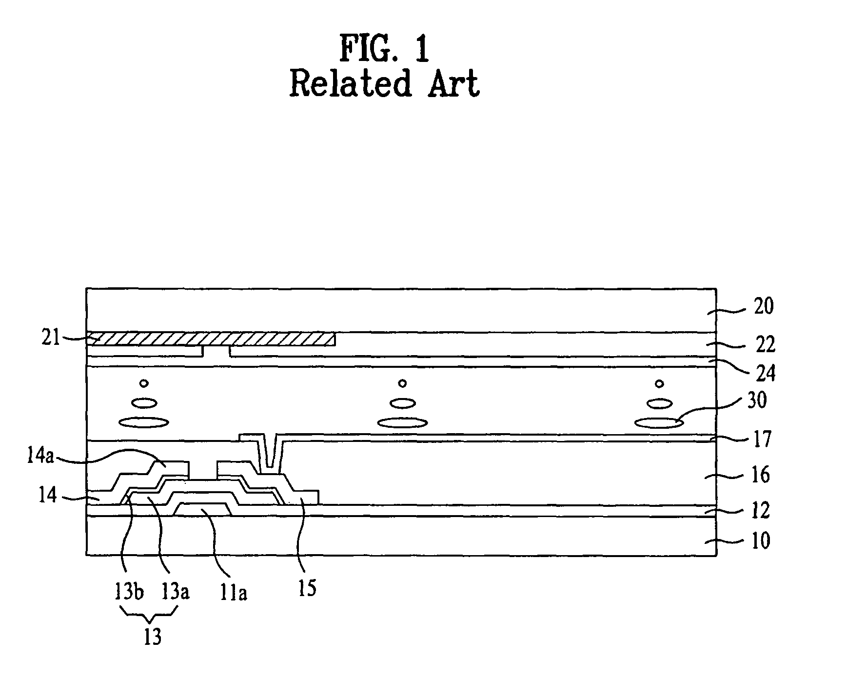
However, when a user tries to make or read a secret document by use of a computer, PDA, etc. using the related art liquid crystal display device, a problem arises in that the related art liquid crystal display device provides only a wide viewing angle and a risk arises of allowing a person other than the user to see the secret document.

Method used


Image

  • Liquid crystal display device capable of realizing both a wide viewing angle and a narrow viewing angle
  • Liquid crystal display device capable of realizing both a wide viewing angle and a narrow viewing angle
  • Liquid crystal display device capable of realizing both a wide viewing angle and a narrow viewing angle

Examples


first embodiment

[0032]The liquid crystal display device according to the present invention is configured such that a plurality of pixels are defined in a matrix form, and each pixel includes red, green, blue, and white sub-pixels arranged adjacent to one another vertically and horizontally. The liquid crystal display device includes a first substrate (not shown), a second substrate 110, and a third substrate 120, which are stacked in this sequence from the bottom. The liquid crystal display device further includes a thin-film transistor array (not shown) formed on the first substrate, a black matrix 112 formed on the second substrate 110 between the first substrate and the second substrate 110 at the boundary of the respective sub-pixels, color filter layers 114a, 114b, 114c, and 114d formed on the second substrate 110 between the first substrate and the second substrate 110 at the respective sub-pixels, and a barrier layer 122 formed on the third substrate 120 at the overall region of each white s...

second embodiment

[0049]Hereinafter, a liquid crystal display device according to the present invention to solve the above described problem will be described.

[0050]FIG. 6 is a plan view illustrating a liquid crystal display device according to a second embodiment of the present invention. FIG. 7 is a sectional view taken along the line III-III′ of FIG. 6, and FIG. 8 is a sectional view taken along the line IV-IV′ of FIG. 6, illustrating the liquid crystal display device according to the second embodiment of the present invention.

[0051]Similar to that of the previously described first embodiment, the liquid crystal display device according to the second embodiment of the present invention is configured such that a plurality of pixels are defined in a matrix form, and each pixel includes red, green, blue, and white sub-pixels arranged adjacent to one another vertically and horizontally. The liquid crystal display device includes a first substrate (not shown), a second substrate 210, and a third substr...


PUM

PropertyMeasurementUnit
angleaaaaaaaaaa
angleaaaaaaaaaa
sizeaaaaaaaaaa

Abstract

A liquid crystal display device, in which a plurality of pixels are defined in a matrix form and each pixel includes red, green, blue, and white sub-pixels adjacent to one another vertically and horizontally, is disclosed. The liquid crystal display device includes first, second, and third substrates sequentially stacked from the bottom, a thin-film transistor array formed on the first substrate, a black matrix formed on the second substrate between the first substrate and the second substrate at the boundary of the respective sub-pixels, a color filter layer formed on the second substrate between the first substrate and the second substrate at the respective sub-pixels, and a barrier layer formed on the third substrate over each white sub-pixel. An opening in the white sub-pixel has a smaller size than that of openings in the red, green, and blue sub-pixels. Also, an angle defined between a normal line of the second substrate and a line that connects an edge of the barrier layer with an edge of the black matrix formed below the barrier layer is larger than a value calculated by subtracting 5 degrees from an angle causing the total reflection of light to be passed through the second substrate.

Description

[0001]This application claims the benefit of Korean Patent Application No. P2007-0060513, filed in Korea on Jun. 20, 2007, which is hereby incorporated by reference for all purposes as if fully set forth herein.BACKGROUND OF THE INVENTION[0002]1. Field of the Invention[0003]The present invention relates to a liquid crystal display device, and more particularly, to a liquid crystal display device capable of realizing both a wide viewing angle and a narrow viewing angle according to a variety of uses thereof.[0004]2. Discussion of the Related Art[0005]With the development of an Information-Society, the demands for display devices are gradually increasing. Recently, in order to satisfy these demands, different varieties of flat-panel display devices including, for example, a liquid crystal display device, a plasma display panel, an electro-luminescent display device and a vacuum fluorescent display device, have been researched and introduced. Some of them have already been implemented ...

Claims


Application Information

Patent Timeline
Patent Type & Authority Patents(United States)
IPC IPC(8): G02F1/1333G02F1/1335
CPCG02F1/1323G02F1/133512G09G3/3611G02F2001/133562G02F2201/52G09G2300/0426G09G2300/0452G02F1/133562G02F1/1335
Inventor WOO, JONG HOONLEE, YOUNG BOK
Owner LG DISPLAY CO LTD
Learn More