Method and device for filling containers

a technology for filling containers and containers, applied in the direction of liquid bottling, packaging goods, special packaging, etc., can solve the problems of increasing the number of tablets which should be present according to the production quality standard, the quality characteristics defined for the filling process are no longer the same as the actual number of tablets, and quality is increased. , to achieve the effect of increasing the level of process stability

Active Publication Date: 2013-03-26
UHLMANN PAC SYST
View PDF16 Cites 0 Cited by
  • Summary
  • Abstract
  • Description
  • Claims
  • Application Information

AI Technical Summary

Benefits of technology

[0009]It is an object of the present invention to provide an improved method for filling a plurality of containers in cycles, namely a method which is robust, relatively simple, and not susceptible to breakdown, which conveys the filled containers onward without loss of content, and which thus contributes to an increased level of process stability and quality. It is also an object of the invention to provide a corresponding device.
[0019]By means of the method and the device according to the invention, the travel distances are reduced, and accordingly the acceleration of the filled containers is decreased without any negative effect on the filling capacity of the process. The probability that the bulk product already in a container can escape from the container as a result of its rapid movement is therefore significantly reduced. This guarantees in turn that the filling operation can achieve a very high level of quality.
[0020]The number x of filling units F1, F2, . . . , Fx may be odd, and the step length z corresponds to the second spacing d of the containers multiplied by the number x of filling units F1, F2, . . . , Fx. The control is very simple because of the constant step length and can be realized by simple means.
[0021]In another embodiment the number x of filling units F1, F2, . . . , Fx is even and the step length z corresponds alternately to the second spacing d of the containers multiplied by the number x of filling units F1, F2, . . . , Fx minus 1 and the second spacing d of the containers multiplied by the number x of filling units F1, F2, . . . , Fx plus 1, either in this order or in the reverse order. In this way, the method and the device can be adapted relatively easily to the preexisting units of a filling plant, so that there is no need to rebuild it or to reduce its filling capacity.
[0023]It is also advantageous for the first conveyor device to be designed as a slide, which moves slowly by a translational movement in the direction opposite the transport direction during the filling operation and then moves faster in the transport direction to move the containers in cycles.
[0027]The advantage of the device according to the invention consists primarily in that the speed at which the filled containers move can be significantly reduced, i.e., by at least half, as a result of the decrease in the distance which they must travel. As a result, the acceleration is also decreased and thus also is the probability that tablets, for example, could fall out of the filled containers as a result of the centrifugal forces which occur over the conveying distance. At the same time, the method according to the invention guarantees that the filling capacity or overall output of the device in the process chain is not impaired. Overall, therefore, a more stable and higher-quality filling operation is achieved.

Problems solved by technology

The disadvantage of this is that the group of bottles already filled with tablets undergoes considerable acceleration as a result of the rapid translational movements of the slide and of the endless conveyor chain, which are both moving in the same direction and the speeds of which are therefore additive.
There is thus the risk that the number of tablets which should be present according to the production quality standard is no longer the same as the number of tablets actually present.
The quality characteristics defined for the filling process therefore cannot be maintained.

Method used


Image

  • Method and device for filling containers
  • Method and device for filling containers
  • Method and device for filling containers

Examples


Embodiment Construction

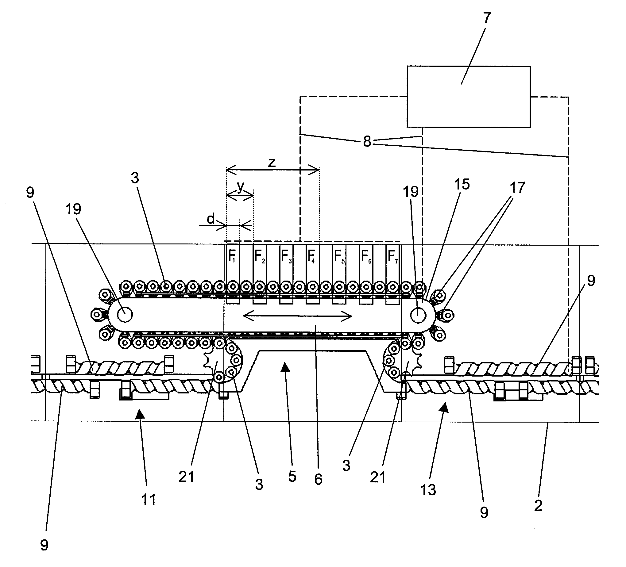
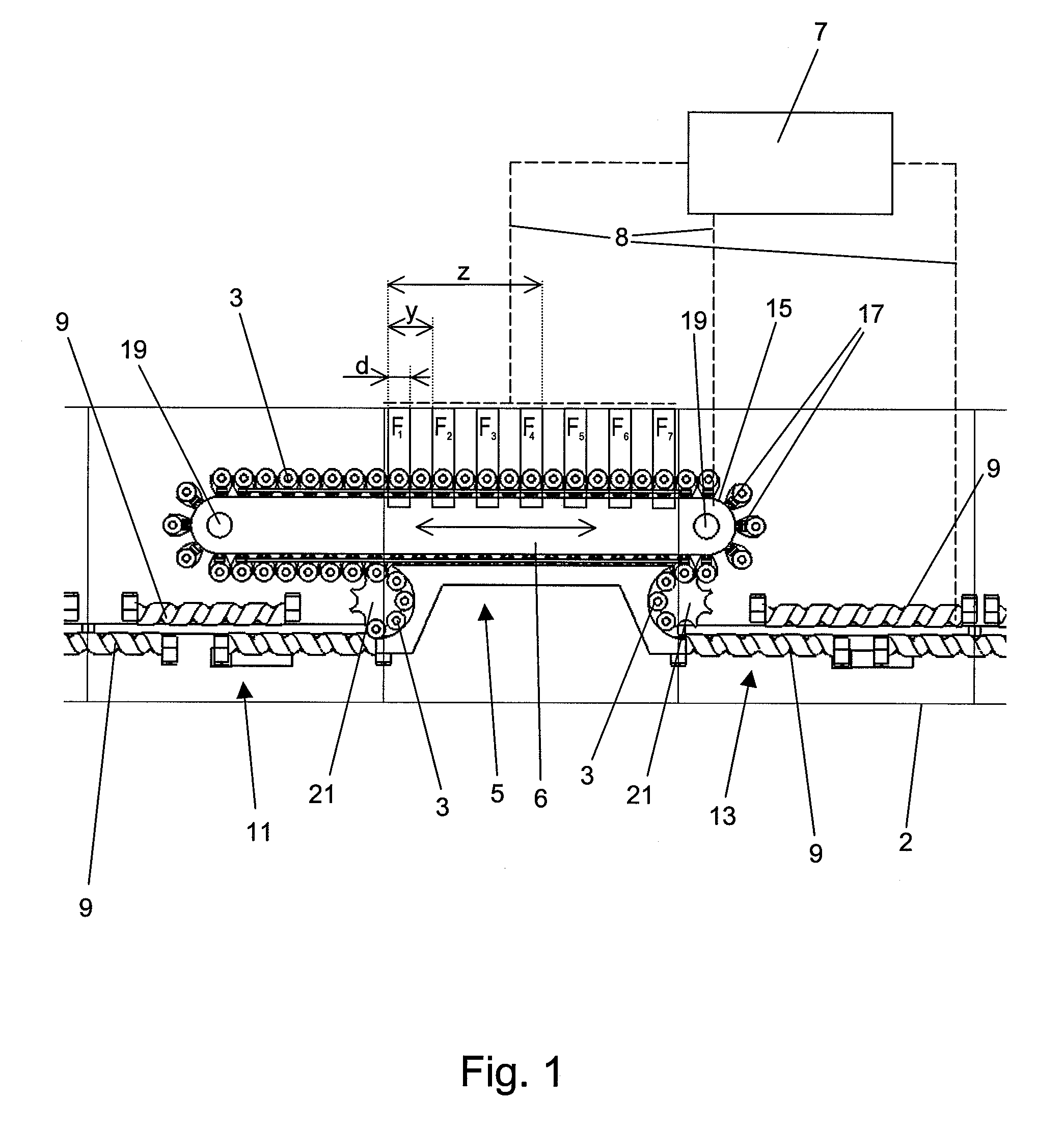
[0034]FIG. 1 is a top view of a preferred embodiment of the device according to the invention for filling in cycles of a plurality of containers positively guided one-by-one. The device of the preferred embodiment shown in FIG. 1 represents a portion of a plant for filling bottle-like or tin-like containers with pharmaceutical products.

[0035]In the intake area inside a housing 2 shown on the left in FIG. 1, a second conveyor device 11 uses screw conveyors 9 to guide the containers 3 being supplied continuously one-by-one from the left to a first conveyor device 5. In the discharge area (on the right in FIG. 1), the containers 3 are transferred from the first conveyor device 5 to the third conveyor device 13, which also comprises screw conveyors 9. In the transfer area between the second conveyor device 11 and the first conveyor device 5 and between the first conveyor device 5 and the third conveyor device 13, there is in each case a star wheel 21 with holders for the positively guid...


PUM

PropertyMeasurementUnit
step lengthaaaaaaaaaa
step widthaaaaaaaaaa
movementaaaaaaaaaa

Abstract

A method for filling a plurality of containers in cycles at a predetermined number of stationary filling units arranged in a row with a first spacing from each other. The method includes providing a plurality of positively guided containers in a row, one-by-one, wherein the containers have a uniform second spacing from each other, wherein the first spacing of the individual filling units is a whole-number multiple of the second spacing of the containers, and filling a predetermined number of the containers simultaneously at the filling units. The containers are shifted in cycles along the filling units in a transport direction by a step length, which is a whole-number multiple of the second spacing of the containers and which is shorter than a third spacing between a first filling unit and a last filling unit steps of filling and shifting are repeated over a predetermined number of iterations.

Description

BACKGROUND OF THE INVENTION[0001]1. Field of the Invention[0002]The present invention pertains to a method and to a device for filling a plurality of containers in cycles, especially for use in the packaging of pharmaceutical products.[0003]2. Description of the Related Art[0004]These types of devices have been used for many years, and in the pharmaceutical industry they serve, for example, to fill bottles or tins with tablets. In the standard case, a conveyor belt or screw conveyor, moving in cycles, is used, which carries the containers to be filled to stationary filling stations and takes them away again. Examples of these types of filling devices are known from EP 1 035 023 A1 and WO 2006 / 016268 A1.[0005]So that the highest possible throughput can be achieved during production and so that there is no need to interrupt the continuous transport of the containers before and after they have been filled as described above, the containers to be filled can be transferred to an intermed...

Claims


Application Information

Patent Timeline
Patent Type & Authority Patents(United States)
IPC IPC(8): B65B3/04
CPCB65B5/103B65B43/52B65B43/56B65G47/082B65G47/5127
Inventor NOE, JOACHIMRUELKER, THOMASHEIM, RALF
Owner UHLMANN PAC SYST
Why Eureka
Try Eureka