Three-dimensional magnet structure and associated method

a three-dimensional magnet and structure technology, applied in the field of magnets, can solve the problems of reducing the cost of electric motors and generators utilized in renewable energy applications, and achieve the effects of increasing the magnetic flux, improving efficiency, and increasing the size and weight of magnets

Active Publication Date: 2013-03-26
THE BOEING CO
View PDF7 Cites 31 Cited by
  • Summary
  • Abstract
  • Description
  • Claims
  • Application Information

AI Technical Summary

Benefits of technology

[0006]According to embodiments of the present invention, a magnet structure is provided that is comprised of a plurality of individual magnets arranged in a configuration that may provide increased levels of magnetic flux without necessarily a corresponding increase in the size and weight of the magnet. A corresponding method of utilizing a magnet structure is also provided according to one embodiment. By providing magnet structures that may provide improved efficiency with increased flux density without corresponding increases in the size and weight, improved electric motors and generators incorporating such magnet structures may be provided, thereby facilitating performance improvements in the applications in which such electric motors and generators are utilized, such as vehicular applications, renewable energy applications and the like.

Problems solved by technology

Similarly, in renewable energy applications that utilize electric motors or generators, a magnet structure offering improved performance and efficiency with no corresponding increase in weight may correspondingly improve the performance and potentially decrease the cost of the electric motors and generators utilized in the renewable energy applications.

Method used


Image

  • Three-dimensional magnet structure and associated method
  • Three-dimensional magnet structure and associated method
  • Three-dimensional magnet structure and associated method

Examples


Embodiment Construction

[0024]The present inventions now will be described more fully hereinafter with reference to the accompanying drawings, in which some, but not all embodiments of the inventions are shown. Indeed, these inventions may be embodied in many different forms and should not be construed as limited to the embodiments set forth herein; rather, these embodiments are provided so that this disclosure will satisfy applicable legal requirements. Like numbers refer to like elements throughout.

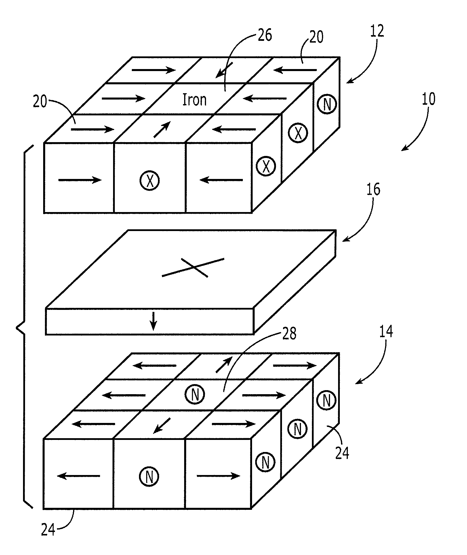
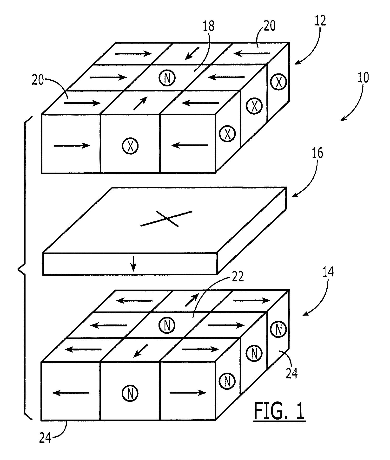
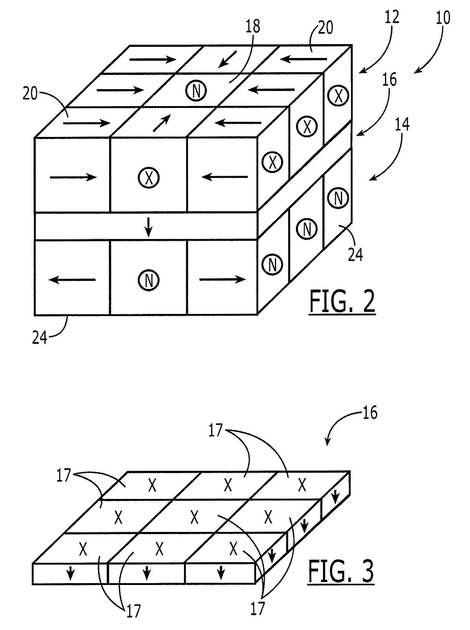
[0025]Referring now to FIGS. 1 and 2, a magnet structure 10 is depicted in accordance with one embodiment of the present invention. The magnet structure includes first and second layers 12, 14 of magnets positioned in planar arrays on opposite side of a planar magnet 16 and oriented in such a manner as to provide an improved or increased magnetic flux field. Each layer of magnets includes a pole magnet 18, 22 and a plurality of additional magnets 20, 24 positioned about the pole magnet. In the embodiment depic...


PUM

PropertyMeasurementUnit
sizesaaaaaaaaaa
magnetic fieldaaaaaaaaaa

Abstract

A magnet structure is provided that includes a first layer of magnets including a first pole magnet and a plurality of first magnets that are positioned about the first pole magnet. The plurality of first magnets are oriented to have respective magnetic fields directed inward relative to the first pole magnet. The magnet structure may also include a second layer of magnets including a second pole magnet and a plurality of second magnets positioned about the second pole magnet and oriented such that the plurality of second magnets have respective magnetic fields directed outward relative to the second pole magnet. The magnet structure may also include a planar magnet positioned between the first and second layers of magnets and oriented such that the planar magnet repels each of the first and second layers of magnets. A magnet assembly and an associated method are also provided.

Description

TECHNOLOGICAL FIELD[0001]Embodiments of the present invention relate generally to magnets and, more particularly, to three-dimensional magnet structures and associated methods.BACKGROUND[0002]A variety of magnets are utilized in an increasing number of applications including, for example, in the stator and rotor of electric motors and generators. In this regard, with the growing interest in electric vehicles and in renewable energy applications that utilize electric motors and generators, the demand for magnets is correspondingly growing.[0003]The magnets utilized in the stator and rotor of electric motors and generators may include permanent magnets formed of various materials, such as rare earth neodymium iron boron in order to increase the flux density in the air gap. The magnets may also be arranged in a Halbach array, arranged to have a dual flux path, or configured to have an iron backing or a yoke so as to further increase the flux density in the air gap.[0004]In many applica...

Claims


Application Information

Patent Timeline
Patent Type & Authority Patents(United States)
IPC IPC(8): H01F7/02
CPCH01F7/0273
Inventor CLEVELAND, MARK ALLEN
Owner THE BOEING CO
Why Eureka
Try Eureka