Resonator assembly for mitigating dynamics in gas turbines

a technology of resonance assembly and gas turbine, which is applied in the direction of machines/engines, mechanical equipment, lighting and heating apparatus, etc., can solve the problems of limiting the life and/or system operability of the hardware of the engine, mechanical and thermal fatigue, and combustor hardware damag

Active Publication Date: 2013-04-02
GE INFRASTRUCTURE TECH INT LLC
View PDF16 Cites 18 Cited by
  • Summary
  • Abstract
  • Description
  • Claims
  • Application Information

AI Technical Summary

Benefits of technology

[0010]Another exemplary embodiment of the present invention concerns a method for suppressing the dynamic interaction of cans among combustor cans in a gas turbine combustion engine. Such method comprises a step of providing a plurality of consecutively arranged combustor cans for generating respective streams of combustion gases therein and collectively discharging the streams of combustion gases. A plurality of resonators is also provided for being operatively coupled to selected ones of the combustor cans. The plurality of resonators are then selectively tuned to suppress one or more of out-of-phase and in-phase dynamic interaction of the streams discharged from adjacent cans in the plurality of consecutively arranged combustor cans.

Problems solved by technology

Such high dynamics can limit hardware life and / or system operability of an engine, causing such problems as mechanical and thermal fatigue.
Combustor hardware damage can come about in the form of mechanical problems relating to fuel nozzles, liners, transient pieces, transient piece sides, radial seals, impingement sleeves, and others.
These problems can lead to damage, inefficiencies, or blow outs due to combustion hardware damage.
Although resonator assemblies have been used, their application has apparently been limited to the attenuation of high frequency instabilities by pure absorption of acoustic energy.

Method used


Image

  • Resonator assembly for mitigating dynamics in gas turbines
  • Resonator assembly for mitigating dynamics in gas turbines
  • Resonator assembly for mitigating dynamics in gas turbines

Examples


Embodiment Construction

[0028]Reference is now made to particular embodiments of the invention, one or more examples of which are illustrated in the drawings. Each embodiment is presented by way of explanation of aspects of the invention, and should not be taken as a limitation of the invention. For example, features illustrated or described with respect to one embodiment may be used with another embodiment to yield a still further embodiment. It is intended that the present invention include these and other modifications or variations made to the embodiments described herein.

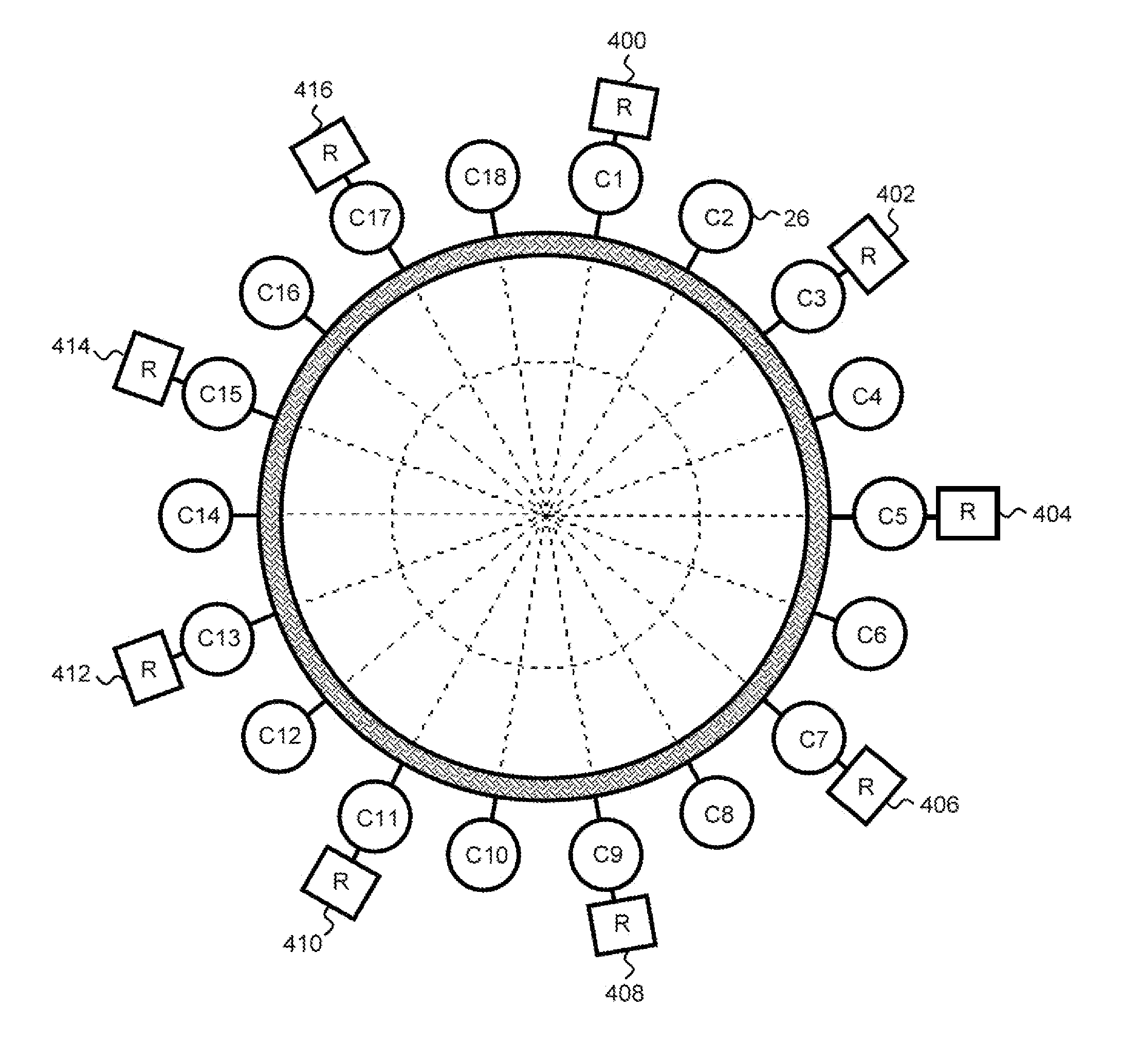
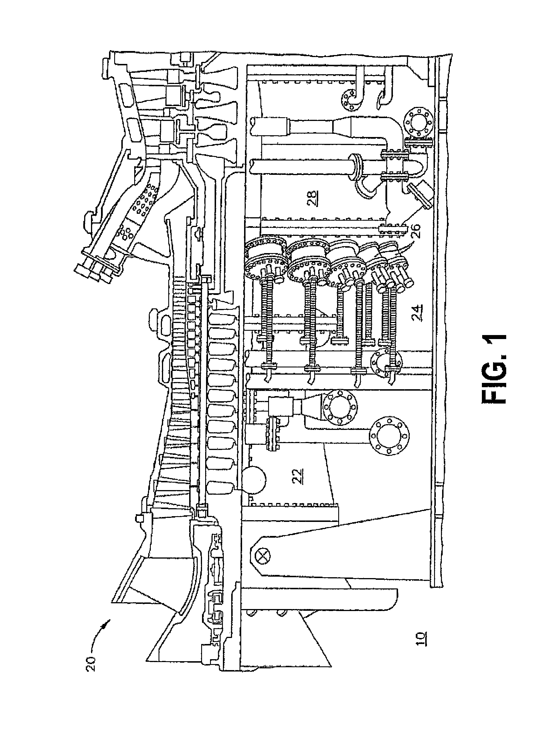
[0029]FIG. 1 is a side cutaway view of a gas turbine engine system 10 that includes a gas turbine engine 20. Gas turbine engine 20 includes a compressor section 22, a combustor section 24 including a plurality of combustor cans 26, and a turbine section 28 coupled to compressor section 22 using a shaft (not shown).

[0030]In operation, ambient air is channeled into compressor section 22 wherein the ambient air is compressed to a pressur...


PUM


Abstract

A combustor for a gas turbine engine and related method is provided in which a plurality of combustor cans are selectively adapted with corresponding resonators. The resonators may, for example, be attached to every can in the consecutive arrangement of combustor cans, every other can, every third can or the like, and may be tuned to the same or first, second, third, etc. frequencies of operation. Such selective tuning is configured to suppress one or more of out-of-phase and in-phase dynamic interaction of streams discharged from adjacent combustor cans by changing the frequencies of pressure oscillation instabilities across the arrangement of consecutive cans.

Description

FIELD OF THE INVENTION[0001]The subject matter disclosed herein relates to combustion dynamics control, and more particularly, to systems and methods for using resonators to reduce dynamics within a multi-can combustor.BACKGROUND[0002]In a gas turbine engine, air is pressurized in a compressor and mixed with fuel in a combustor for generating hot combustion gases that flow downstream through turbine stages where energy is extracted. Large industrial power generation gas turbine engines typically include a can combustor having a row of individual combustor cans in which combustion gases are separately generated and collectively discharged. Since the can combustors are independent and discrete components, each generating its respective combustion heat stream, the static and dynamic operation of the cans are inter-related.[0003]Of particular concern to effective operation of can combustor engines is combustion dynamics, i.e., dynamic instabilities in operation. High dynamics are often ...

Claims


Application Information

Patent Timeline
Patent Type & Authority Patents(United States)
IPC IPC(8): F02C3/00F23R3/46
CPCF23R3/002F23M20/005F23R2900/00014F23R2900/00013
Inventor DAVIS, JR., LEWIS BERKLEYHAN, FEISRINIVASAN, SHIVASINGH, KAPIL KUMARKIM, KWANWOONARRA, VENKATESWARLU
Owner GE INFRASTRUCTURE TECH INT LLC
Why Eureka
Try Eureka