Trolley-type conveyance device

a conveyancing device and trolley-type technology, applied in the direction of lighting and heating equipment, furniture, charge manipulation, etc., can solve the problems of high cost of the conveying carriage itself, the large number of conveying carriages, and the overall equipment cost, so as to reduce equipment cost and improve safety. , the effect of small number

Active Publication Date: 2013-04-02
DAIFUKU CO LTD +1
View PDF18 Cites 19 Cited by
  • Summary
  • Abstract
  • Description
  • Claims
  • Application Information

AI Technical Summary

Benefits of technology

[0005]The conveying carriage with the elevatable workpiece support base used in the automobile assembly line is made to travel in such a manner that the rear of a preceding conveying carriage and the front of a following conveying carriage butt against each other. Thus, a considerable number of conveying carriages are needed in the automobile assembly line. When the conventional configuration as described in Patent Document 1 is employed in such a conveying carriage, a motor for vertically driving the workpiece support base has to be installed on each of a considerable number of conveying carriages. This results in a high cost of the conveying carriage itself and, eventually, the entire equipment.
[0007]When the afore-described present invention is carried out, the locking means (23) can easily be realized by interposing a worm gear reducer (44) in a transmission system between the driving shaft (43) of the elevating drive means (3) and the passive shaft (22). Further, the synchronization drive means to make the conveying carriage (1) and the power source carriage (52) synchronously travel at each workpiece support height changing position can be achieved by a means to electrically synchronously control a driving motor for a travel drive means provided to the power source carriage (52). When the synchronization drive means (60) is configured by a couplable and separable coupling means (62) to couple the conveying carriage (1) and the power source carriage (52), however, the conveying carriage and the power source carriage are mechanically coupled and integrated, and the both can steadily be made to travel synchronously.
[0012]According to the configuration of the present invention, the need to install a power source such as an electric motor for vertically driving the elevatable workpiece support base provided to the conveying carriage, on the conveying carriage is eliminated. The power source has only to be installed on the power source carriage juxtaposed at each workpiece support height changing position and being remarkably small in number compared with the conveying carriages for the entire equipment. Even if the power source carriage has to be juxtaposed at each workpiece support height changing position, the number of power sources such as electric motors used can be reduced significantly for the entire equipment, whereupon equipment cost reduction can be achieved. Furthermore, on the traveling path other than each workpiece support height changing position, not only is an accidental descent of the workpiece support base avoided by the locking means but also a fear of causing unexpected occurrences such as the workpiece support base being vertically driven due to a control system failure or a worker's misoperation is eliminated, whereupon safety is further improved.

Problems solved by technology

Thus, a considerable number of conveying carriages are needed in the automobile assembly line.
This results in a high cost of the conveying carriage itself and, eventually, the entire equipment.

Method used


Image

  • Trolley-type conveyance device
  • Trolley-type conveyance device
  • Trolley-type conveyance device

Examples


Embodiment Construction

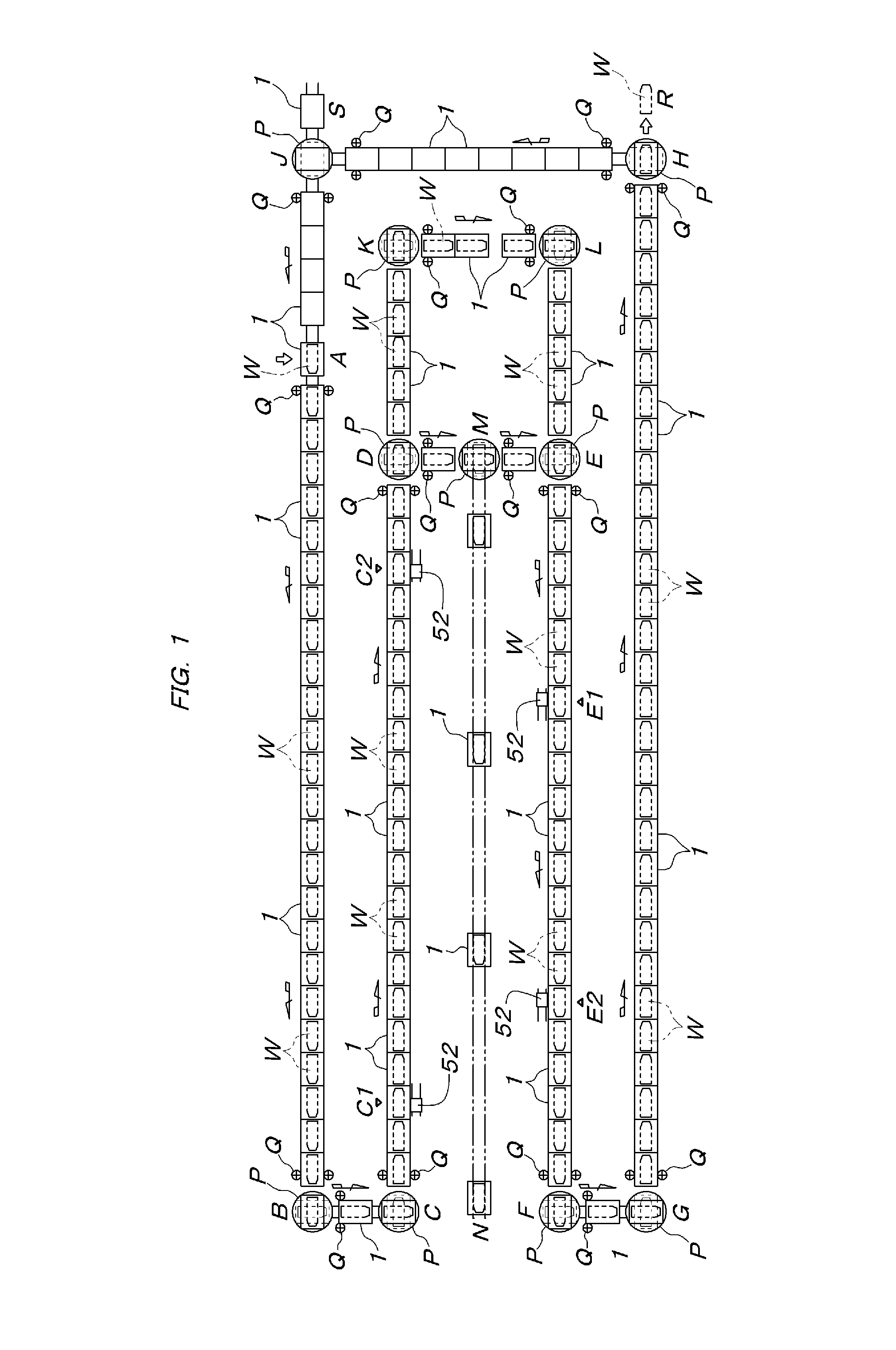
[0039]An automobile assembly line as shown in FIG. 1 consists of an endless circulating traveling path for conveying carriages 1. The line includes a first working section A-B, a first relay section B-C, a second working section C-D, a second relay section D-E, a third working section E-F, a third relay section F-G, a fourth working section G-H, and an empty conveying carriage returning section H-J-A. A buffer section D-K-L-E is connected with the second relay section D-E in parallel. An auxiliary section M-N which is temporarily used diverges from the second relay section D-E. Conveying carriage deflectors P as referred to as turntables are respectively arranged at both ends B to G of each relay section B-C, D-E, or F-G, at the beginning end H and an intermediate turning point J of the empty conveying carriage returning section H-J-A, at intermediate turning points K and L of the buffer section D-K-L-E, and at the beginning end M of the auxiliary section M-N.

[0040]The conveying car...


PUM


Abstract

A carriage-type conveying apparatus with a workpiece support base and an elevating drive has a passive shaft interlocked with the elevating drive and a lock to prevent descent of the workpiece support base A power source carriage capable of traveling synchronously with the conveying carriage is aside of a traveling path of the conveying carriage at a workpiece support height changing position so as to be reciprocable along the traveling path. The power source carriage has a transmission shaft driven by a power source and a separable interlock to interlock the passive shaft and a transmission shaft with each other.

Description

CROSS-REFERENCE TO RELATED APPLICATIONS[0001]The present application is a continuation of pending International patent application PCT / CN2011 / 001138 filed on Jul. 11, 2011 which designates the United States and claims priority from Chinese patent application Nos. 2010 2 0253390.0 filed on Jul. 9, 2010, 2010 2 0253398.7 filed on Jul. 9, 2010, 2010 1 0255351.9 filed on Aug. 17, 2010, 2010 2 0294310.6 filed on Aug. 17, 2010, and 2010 2 00294309.3 filed on Aug. 17, 2010, the contents of which are incorporated herein by reference.FIELD OF THE INVENTION[0002]The present invention relates to a carriage-type conveying apparatus which can be utilized for conveying vehicle bodies in an automobile assembly line.BACKGROUND OF THE INVENTION[0003]A support level of a vehicle body supported on a conveying carriage needs to be variable according to work content with respect to the vehicle body in the carriage-type conveying apparatus which can be used for conveying vehicle bodies in an automobile a...

Claims


Application Information

Patent Timeline
Patent Type & Authority Patents(United States)
IPC IPC(8): B65G29/00
CPCB65G35/06B62D65/18B65G37/02B62D65/00B65G37/00B65G35/00
Inventor MURAKAMI, MASAMIWANG, JIANGUO
Owner DAIFUKU CO LTD
Why Eureka
Try Eureka