Ozone concentrator

a concentrator and concentrator technology, applied in the field of ozone concentrators, can solve problems such as difficulty in storing ozone gas, and achieve the effect of satisfactory energy efficiency and stable ozon

Active Publication Date: 2013-04-02
TOSHIBA MITSUBISHI-ELECTRIC IND SYST CORP
View PDF12 Cites 2 Cited by
  • Summary
  • Abstract
  • Description
  • Claims
  • Application Information

AI Technical Summary

Benefits of technology

[0014]The present invention provides an ozone concentrator including an ozone generator, a plurality of adsorption / desorption columns in which an ozone adsorbent cooled with a certain-temperature refrigerant for concentrating ozone generated by the ozone generator is packed, cooling means for cooling the refrigerant, a vacuum pump connected to the adsorption / desorption columns, for concentrating the ozone in the adsorption / desorption columns by discharging mainly oxygen from the adsorbent adsorbing the ozone, a plurality of valves for air pressure operations, connected to the adsorption / desorption columns, for switching passages of gas that is allowed to flow in or flow out with respect to the adsorption / desorption columns, and an ozone concentration meter for measuring a concentration of the ozone concentrated by the vacuum pump, in which a discharge line of the vacuum pump that concentrates the ozone in one of the adsorption / desorption columns in which the adsorbent is packed is connected to another one of the adsorption / desorption columns, whereby the ozone is allowed to pass through the another one of the adsorption / desorption columns again. Therefore, stable ozone of high concentration can be generated at a satisfactory energy efficiency without any temperature difference between upper and lower positions of adsorption / desorption columns.

Problems solved by technology

It is difficult to store ozone gas in a state of gas due to the strong self-decomposition property thereof, and ozone gas is generally generated for use by an ozone generator in the vicinity of an ozone-using facility.

Method used


Image

  • Ozone concentrator
  • Ozone concentrator
  • Ozone concentrator

Examples


embodiment 1

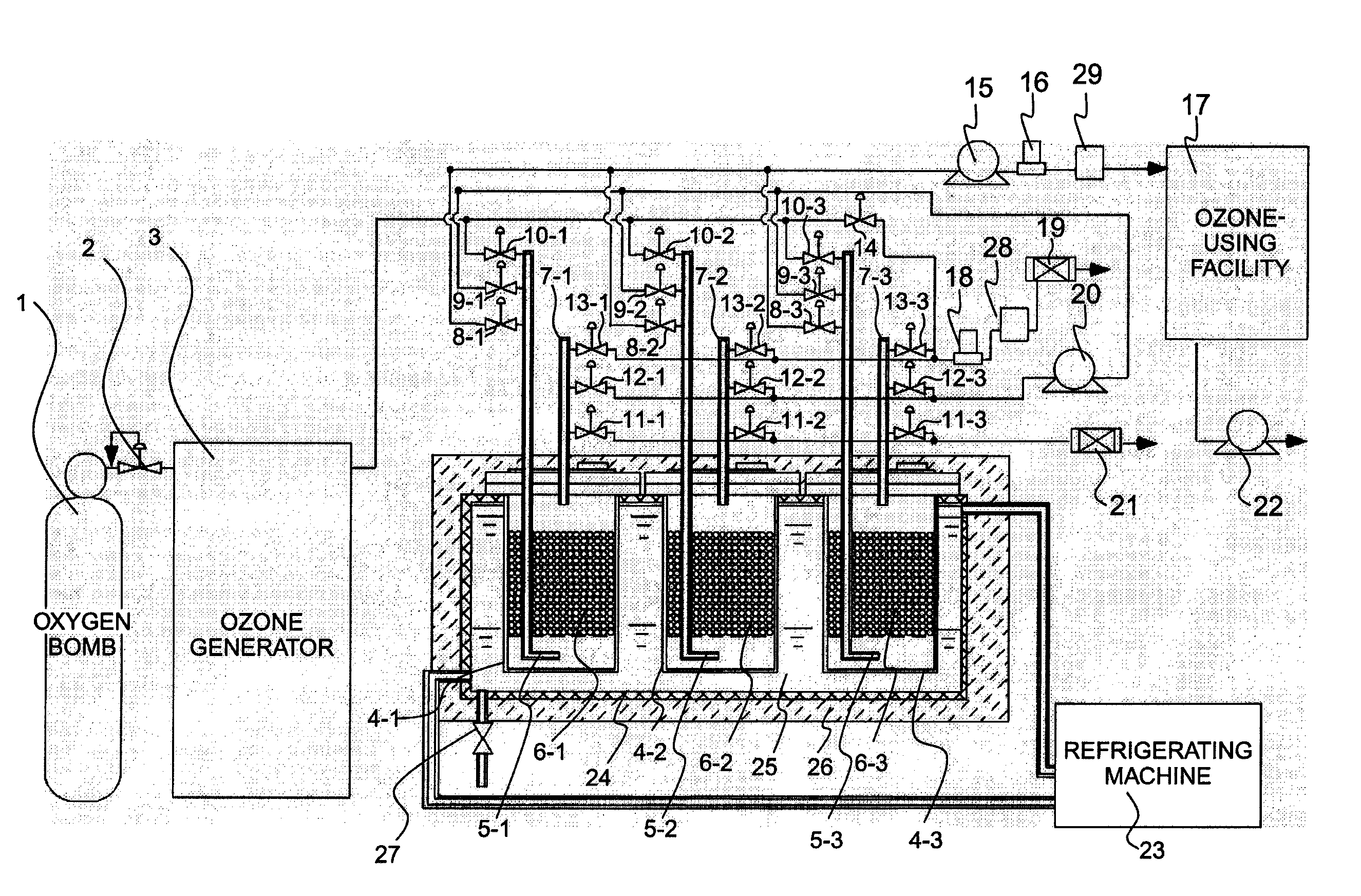
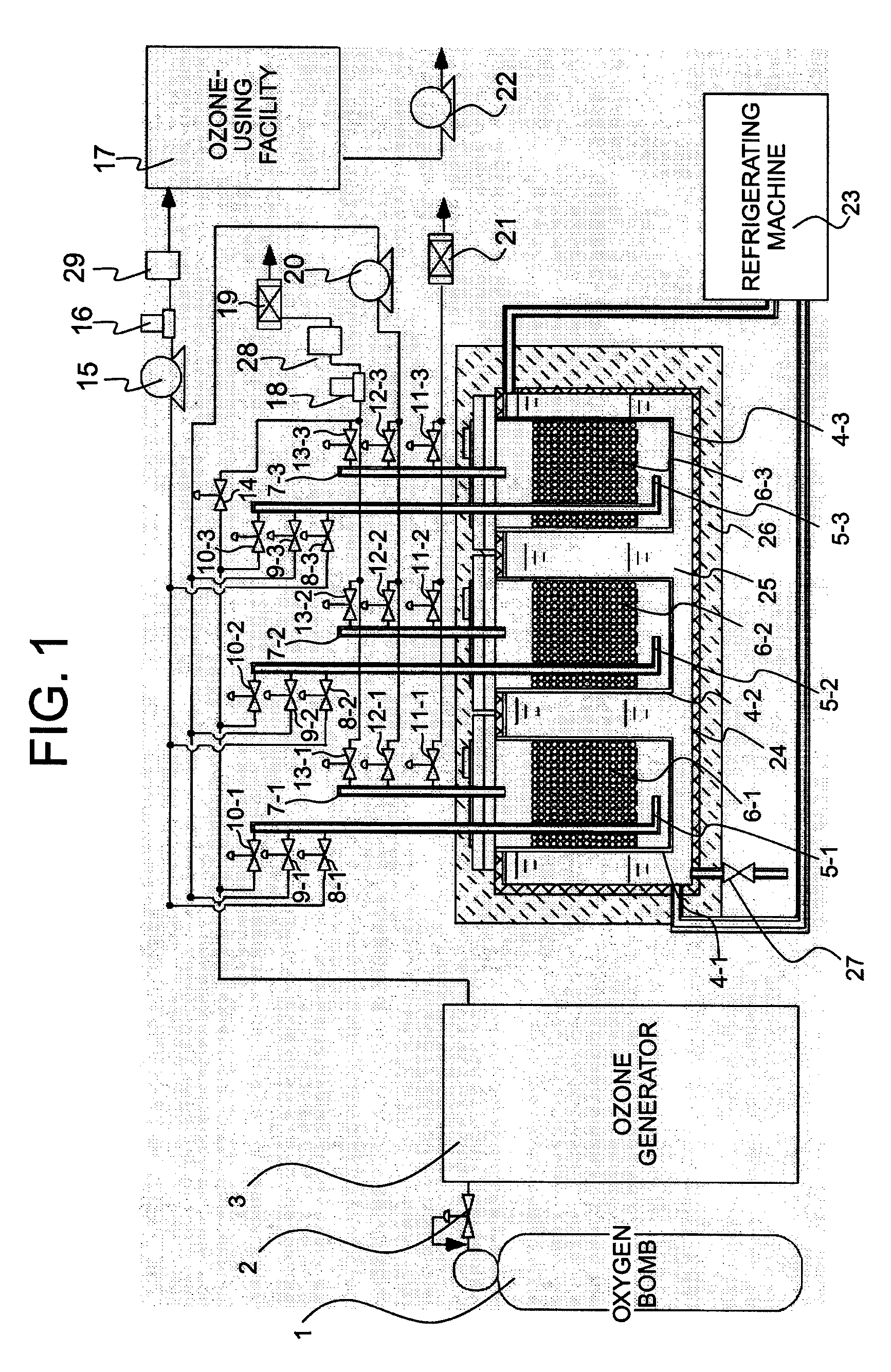
[0021]FIG. 1 is a view illustrating an ozone concentrator according to Embodiment 1 of the present invention. As illustrated in FIG. 1, the ozone concentrator according to Embodiment 1 of the present invention is provided with three adsorption / desorption columns 4. In FIG. 1, although the adsorption / desorption columns are denoted with reference numerals 4-1, 4-2, and 4-3, respectively, they are described collectively as reference numeral 4 in the following description. In the same way as in the other configurations, X-1 denotes a member provided so as to correspond to the adsorption / desorption column 4-1, X-2 denotes a member provided so as to correspond to the adsorption / desorption column 4-2, and X-3 denotes a member provided so as to correspond to the adsorption / desorption column 4-3, and they are collectively denoted simply as X (herein, X indicates numbers of 5 to 13).

[0022]Returning to FIG. 1, the three adsorption / desorption columns 4 are contained in a cooling tank 24 the out...

embodiment 2

[0035]FIG. 3 is a view illustrating an ozone concentrator according to Embodiment 2 of the present invention. The inlet gas communication tube 5 and the outlet gas communication tube 7 are inserted in the adsorption / desorption columns 4-1 to 4-3 from above, the inlet gas communication tube 5 penetrates the silica gel 6 to a lower portion thereof, and a gas introduction port of the communication tube 5 and a gas discharge port of the communication tube 7 are placed with the silica gel 6 interposed therebetween. The adsorption / desorption columns 4-1 to 4-3 are attached to the cooling tank 24 with a plurality of bolts 30. The respective upper ends of the inlet gas communication tube 5 and the outlet gas communication tube 7 outside the adsorption / desorption column 4 are placed on the same side of the adsorption / desorption column 4, and the respective lower ends placed inside the adsorption / desorption column 4 sandwich the silica gel 6, and hence, ozone gas is likely to be adsorbed. Fur...

embodiment 3

[0038]FIG. 5 is a view illustrating an ozone concentrator according to Embodiment 3 of the present invention. As illustrated in FIG. 5, the adsorption / desorption column 4 is inserted so as to be directed horizontally in the cooling tank 24 from a side surface of the cooling tank 24 and attached to the side surface with bolts 30. The configuration of the adsorption / desorption column 4 itself is basically the same as those illustrated in Embodiments 1 and 2. However, in this embodiment, the adsorption / desorption column 4 is placed horizontally, and hence, the silica gel 6 is positioned in a center portion in a height direction (including a diameter in a horizontal direction) in the adsorption / desorption column 4, and is placed while gaps are provided only in upper and lower portions in the adsorption / desorption column 4. In the center portion (excluding the gaps), the silica gel 6 is in close contact with the inner wall of the adsorption / desorption column 4. Further, the outlet gas co...


PUM

PropertyMeasurementUnit
diameteraaaaaaaaaa
gauge pressureaaaaaaaaaa
temperatureaaaaaaaaaa

Abstract

Provided is an ozone concentrator including an ozone generator (3), adsorption / desorption columns (4) in which silica gel (6) cooled with a certain-temperature refrigerant (25) for concentrating ozone generated by the ozone generator (3) is packed, a refrigerating machine (23) for cooling the refrigerant (25), a vacuum pump (20) for enhancing a concentration of the ozone in one of the adsorption / desorption columns (4) by discharging mainly oxygen from the silica gel (6) adsorbing the ozone, a plurality of valves (8) to (13) for air pressure operations, for switching passages of gas that is allowed to flow in or flow out with respect to the adsorption / desorption columns (4), and ozone concentration meters (28, 29) for measuring the concentration of the ozone enhanced by the vacuum pump (20), in which a discharge line of the vacuum pump (20) is connected to another one of the adsorption / desorption columns (4), whereby the ozone is allowed to pass through another one of the adsorption / desorption columns again. Therefore, stable ozone of high concentration can be generated at a satisfactory energy efficiency without any temperature difference between upper and lower positions of adsorption / desorption columns.

Description

TECHNICAL FIELD[0001]The present invention relates to an ozone concentrator that concentrates ozone generated by an ozone generator to produce ozone of high concentration.BACKGROUND ART[0002]In recent years, ozone has been used for a variety of purposes such as cleaning of a silicon wafer used in a semiconductor device, water supply and sewerage treatment, and the like. In cleaning of a silicon wafer, ozone water in which ozone gas is dissolved in pure water is used as a cleaning solution, and hence an organic substance or noble metal on a silicon wafer is removed by using the ozone water together with dilute hydrofluoric acid aqueous solution or the like.[0003]It is difficult to store ozone gas in a state of gas due to the strong self-decomposition property thereof, and ozone gas is generally generated for use by an ozone generator in the vicinity of an ozone-using facility.[0004]A conventional method of concentrating ozone includes an adsorption step of allowing an adsorbent coole...

Claims


Application Information

Patent Timeline
Patent Type & Authority Patents(United States)
IPC IPC(8): B01J19/08
CPCB01D53/047C01B13/10B01D2253/106B01D2259/403B01D2256/14Y02P20/10
Inventor OTA, KOJITANIMURA, YASUHIROTABATA, YOICHIROOKIHARA, YUJIROSAITSU, TETSUYANAKAMURA, NORIYUKIUEDA, RYOHEI
Owner TOSHIBA MITSUBISHI-ELECTRIC IND SYST CORP
Why Eureka
Try Eureka