Adhesive label and method of producing the same

a technology of adhesive labels and adhesive adhesives, applied in the direction of identification means, paper/cardboard containers, instruments, etc., can solve the problems of affecting the operation efficiency, hindering the transportation of adhesive labels, and not disposed of non-adhesive layers, etc., to achieve satisfactory energy efficiency, reduce production costs, and show adhesiveness

Inactive Publication Date: 2012-04-05
SEIKO INSTR INC
View PDF4 Cites 4 Cited by
  • Summary
  • Abstract
  • Description
  • Claims
  • Application Information

AI Technical Summary

Benefits of technology

[0016]According to the present invention, because the surface of the adhesive label is covered with the non-adhesive heat-reactive layer in an environment at room temperature in an unheated state, the adhesive labels do not adhere to each other during storage or transportation. Further, release paper or the like is not necessary, which is preferred in view of the protection of environment, and a production cost can also be reduced. In addition, a desired adhesive region and adhesive strength with satisfactory energy efficiency for exhibiting adhesiveness can be realized easily.

Problems solved by technology

Therefore, it is necessary to peel the release paper, which degrades the efficiency of the operation.
Further, the release paper is coated with a release agent such as silicon, and hence the peeled release paper is disposed of without being recycled as recycled paper or the like, which is waste of resources.
In the case where the paste dirt adheres to the thermal head, the heat of the thermal head becomes unlikely to be transmitted to the thermosensitive adhesive agent layer, and when the paste dirt adheres to the platen roller or a label transport path in the apparatus, the transportation of the adhesive label is hindered.
Therefore, the non-adhesive layer is not disposed of at a time of use.
Therefore, there is a possibility that a part of the adhesive agent layer of the adhesive label adheres to the inside of the transport path to cause paper jam or transport failure.
Further, if the adhesive labels discharged from the adhesive label production apparatus are to be attached in an overlapped manner, the adhesive agent layer of one adhesive label is attached to the non-adhesive layer of the other adhesive label, and hence, the adhesive labels cannot be attached because the one adhesive label does not adhere to the other adhesive label.
Therefore, the heat-reactive layer undergoes thermal contraction from the center of the heating region in which the heating temperature is high to the periphery, and a crack as an opening is formed at the center of the heating region.
However, in the vicinity of the ends of the heating region, the heating temperature is lower than that of the vicinity of the center, and hence, the thermal contraction is unlikely to proceed in the vicinity of the ends of the heating region.
Further, due to the adhesive strength of the adhesive agent layer with respect to the heat-reactive layer, the thermal contraction of the heat-reactive layer is hindered in the vicinity of the interface between the adhesive agent layer and the heat-reactive layer.
Therefore, an opening with an expected size is not formed as compared to the heating region of the thermal head, and the exposure of the adhesive agent layer from the opening of the heat-reactive layer becomes small, resulting in insufficient adhesiveness of the adhesive label.

Method used


Image

  • Adhesive label and method of producing the same
  • Adhesive label and method of producing the same
  • Adhesive label and method of producing the same

Examples


embodiment 1

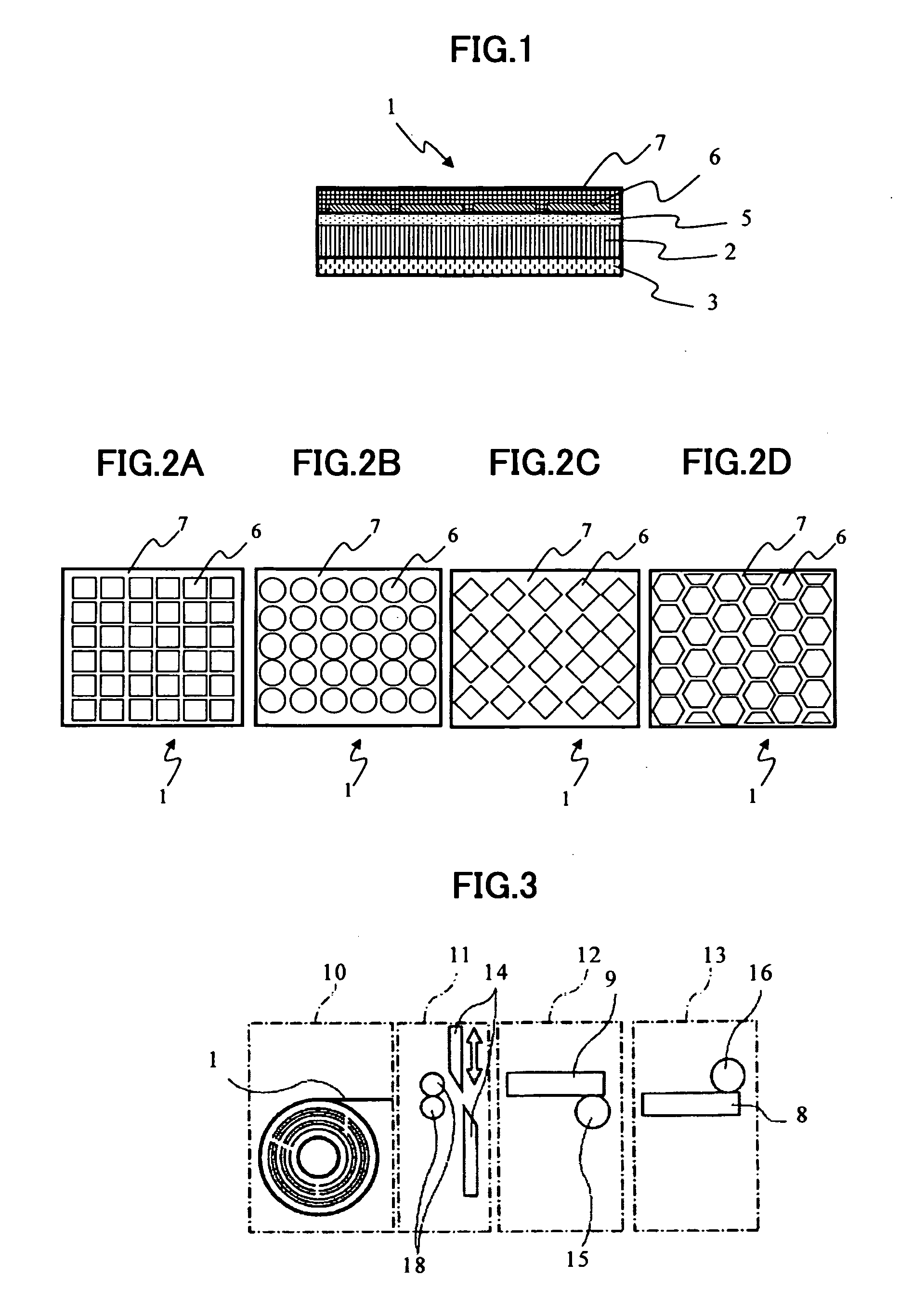
[0035]FIG. 1 is a schematic structural view of an adhesive label according to Embodiment 1 of the present invention.

[0036]An adhesive label 1 has the following configuration. That is, an adhesive agent layer 5 made of a pressure-sensitive adhesive agent, a non-adhesive layer 6, and a non-adhesive heat-reactive layer (resin film layer) 7 made of an olefin-based resin are laminated in the stated order on one surface of a sheet-shaped support 2 made of paper or the like, and a thermosensitive recording layer 3 on which characters, bar codes, and the like are to be recorded is laminated on the other surface of the support 2. An image-receiving layer or the like on which recording is conducted with ink from an ink jet recording device may be used in place of the thermosensitive recording layer 3, and any layer on which recording is conducted may be used.

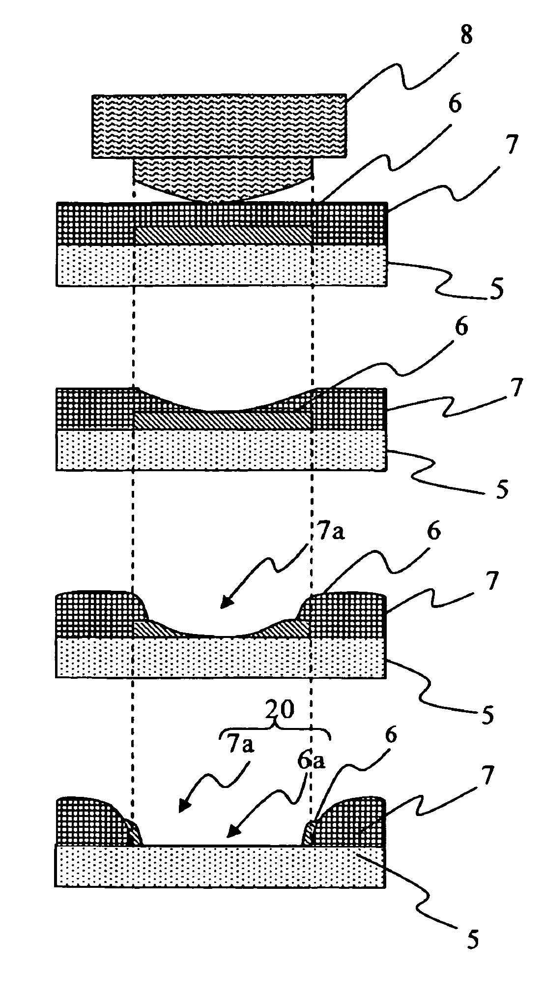
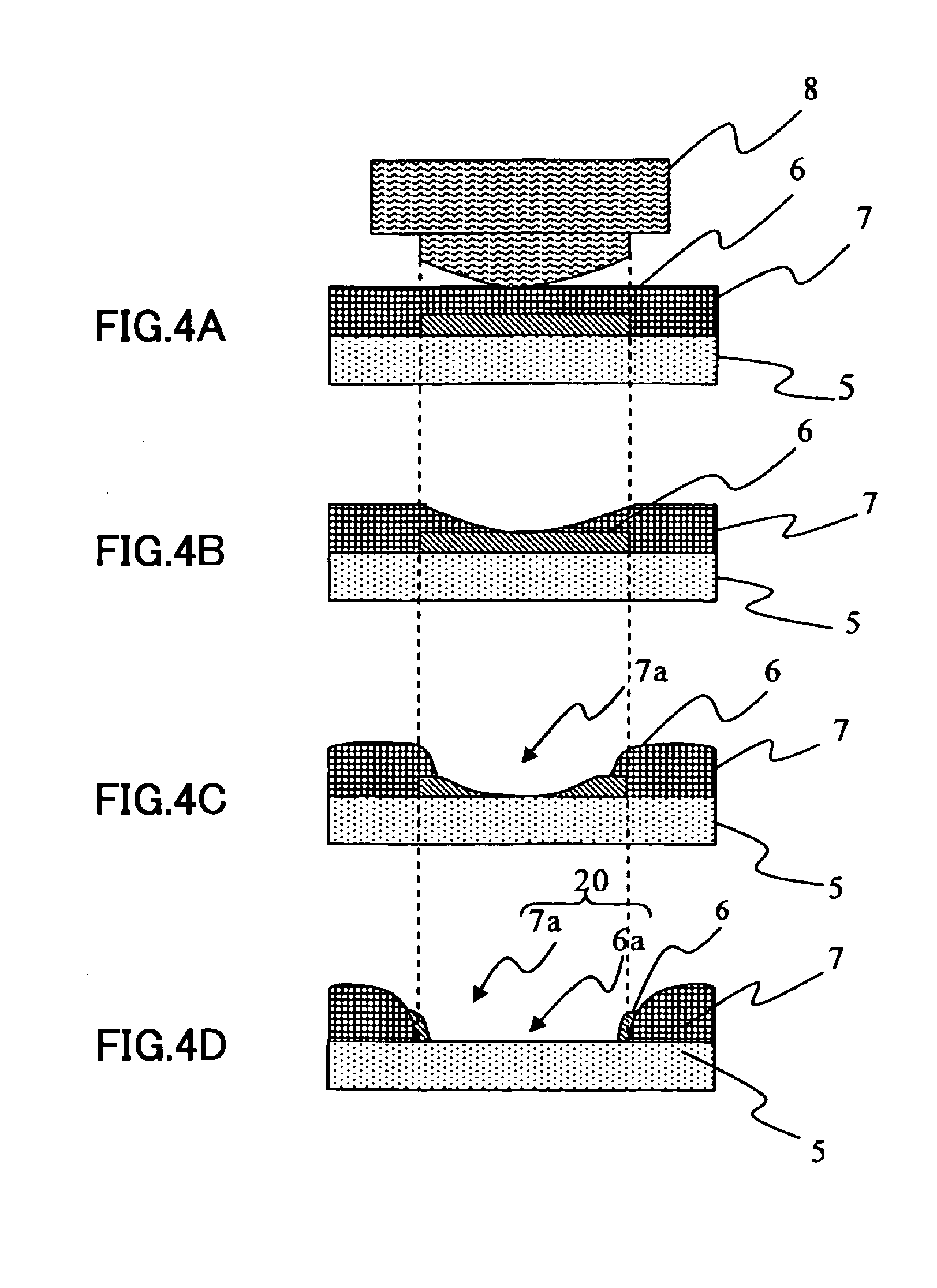
[0037]The non-adhesive layer 6 is not provided uniformly over the entire adhesive label 1, but is disposed on the adhesive agent layer 5...

embodiment 2

[0054]An adhesive label 1 according to Embodiment 2 of the present invention is described. Regarding the components similar to those of Embodiment 1 described above, the descriptions thereof are omitted.

[0055]FIG. 7 is a schematic structural view of an adhesive label 1′ according to Embodiment 2 of the present invention. The adhesive label 1′ has the following configuration. That is, an adhesive agent layer 5 made of a pressure-sensitive adhesive agent, a non-adhesive layer 6, a non-adhesive heat-reactive layer (resin film layer) 7 made of an olefin-based resin, and a slide layer 21 made of the same material as that of the non-adhesive layer 6 or a material with a low friction coefficient are laminated in the stated order on one surface of a sheet-shaped support 2 made of paper or the like, and a thermosensitive recording layer 3 on which characters, bar codes, and the like are to be recorded is laminated on the other surface of the support 2. A method of producing an adhesive label...


PUM

PropertyMeasurementUnit
areaaaaaaaaaaa
thicknessaaaaaaaaaa
thicknessaaaaaaaaaa

Abstract

An adhesive label (1) includes: a support (2); an adhesive agent layer (5) which is made of an adhesive agent, and formed on one surface of the support (2); a non-adhesive heat-reactive layer (7) which is positioned above the adhesive agent layer (5), the non-adhesive heat-reactive layer (7) including an opening formed when heated at a predetermined temperature or higher; and a non-adhesive layer (6) which is positioned between the non-adhesive heat-reactive layer (7) and the adhesive agent layer (5), and is movable over the adhesive agent layer (5).

Description

BACKGROUND OF THE INVENTION[0001]1. Field of the Invention[0002]The present invention relates to an adhesive label and a method of producing the same.[0003]2. Description of the Related Art[0004]Adhesive labels having adhesiveness are widely used for display of bar codes for point-of-sale (POS) of goods such as food, tags for delivery, or display of contents of bottles, cans, etc. The adhesive label generally has the following configuration. That is, an adhesive agent layer that is made of a pressure-sensitive adhesive agent and comes into contact with an article at a time of use, and release paper (separator) to be peeled at the time of use are laminated successively on one surface of a sheet-shaped support, and a thermosensitive recording layer whose color changes upon being heated and on which characters and the like are to be recorded, an image-receiving layer on which recording is conducted with ink from an ink-jet recording device, and the like are laminated on the other surfa...

Claims


Application Information

Patent Timeline
Patent Type & Authority Applications(United States)
IPC IPC(8): B32B3/12B32B38/14B41M5/00B05D3/06B32B7/12G11B5/64B32B37/14B05D5/10
CPCG09F3/10G09F2003/025B32B3/12G09F2003/0247Y10T428/2848Y10T156/10Y10T428/24802Y10T428/24149Y10T428/265G09F2003/026
Inventor SANBONGI, NORIMITSUTANI, KAZUNOSATO, YOSHINORI
Owner SEIKO INSTR INC
Why Eureka
Try Eureka